Philips Semiconductors
AN10369
Philips ARM LPC microcontroller family
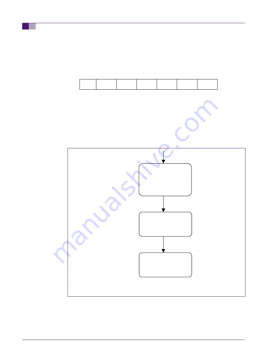
4.2 Setting of the slave address
PCF8574A has the following address
0
1
1
1
A2
A1 A0
In the test setup, A1 was driven high. A2 and A0 are driven low.
4.3 State Diagram (with regard to I
2
C states)
Only three I
2
C states are considered in this example namely 0x8, 0x18 and 0x28. The
code flow is shown below. For detailed description on the I
2
C states, please refer to the
User Manual of the respective device. The section describing I
2
C has been recently
updated for the LPC213x User Manual and this section will be updated for all LPC 2000
Family devices in future revisions of the User Manual.
Start condition transmitted
Fig 4. State diagram code flow
I
2
C master enters
State 8H
and transmits slave
a Write bit
Slave acknowledges
Slave acknowledges
I
2
C master enters
State
28H
and transmits Stop
condition
I
2
C master enters
State
18H
and transmits data
byte 55H
4.4 Code
The files used here are as follows:
1. Interrupt Vector table
© Koninklijke Philips Electronics N.V. 2005. All rights reserved.
Application note
Rev. 01 — 06 April 2005
9 of 17


