Mechanical Instructions
4.
4.3.5
SSB Board Cover Shield (depending on model)
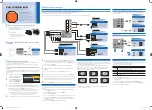
Figure 4-6 Cable clip on cover shield
Figure 4-7 SSB board cover shield
1.
Release the cable from the plastic cable clip (1) on the
shield (see Figure “Cable clip on cover shield” above).
2.
Remove the four fixation screws (2, see Figure “SSB board
cover shield”; the screws are also indicated by arrows on
the shield) and remove the shield.
Notice
that on one side, the shield is not only held by two
screws, but also by two brackets (see Figure “Cable clip on
cover shield” above).
4.3.6
SSB Board
Figure 4-8 SSB board connectors
Figure 4-9 DVI-I connector screws
1.
Very
cautiously
disconnect the LVDS cable (1) from the
panel (see Figure “SSB board connectors”). Notice that this
cable is very fragile.
2.
Disconnect the six remaining cables (2) from the panel.
3.
Remove the fixation screws that secure the SSB board
(depending on model) and also the two fixation screws (3)
from the DVI-I connector on the SSB board (see Figure
“DVI-I connector screws”).
4.
Take the panel out of its brackets.
F_15270_044.eps
180505
1
F_15270_045.eps
190505
2
2
F_15270_046.eps
180505
1
2
2
F_15270_047.eps
180505
3


