231E LCD
5
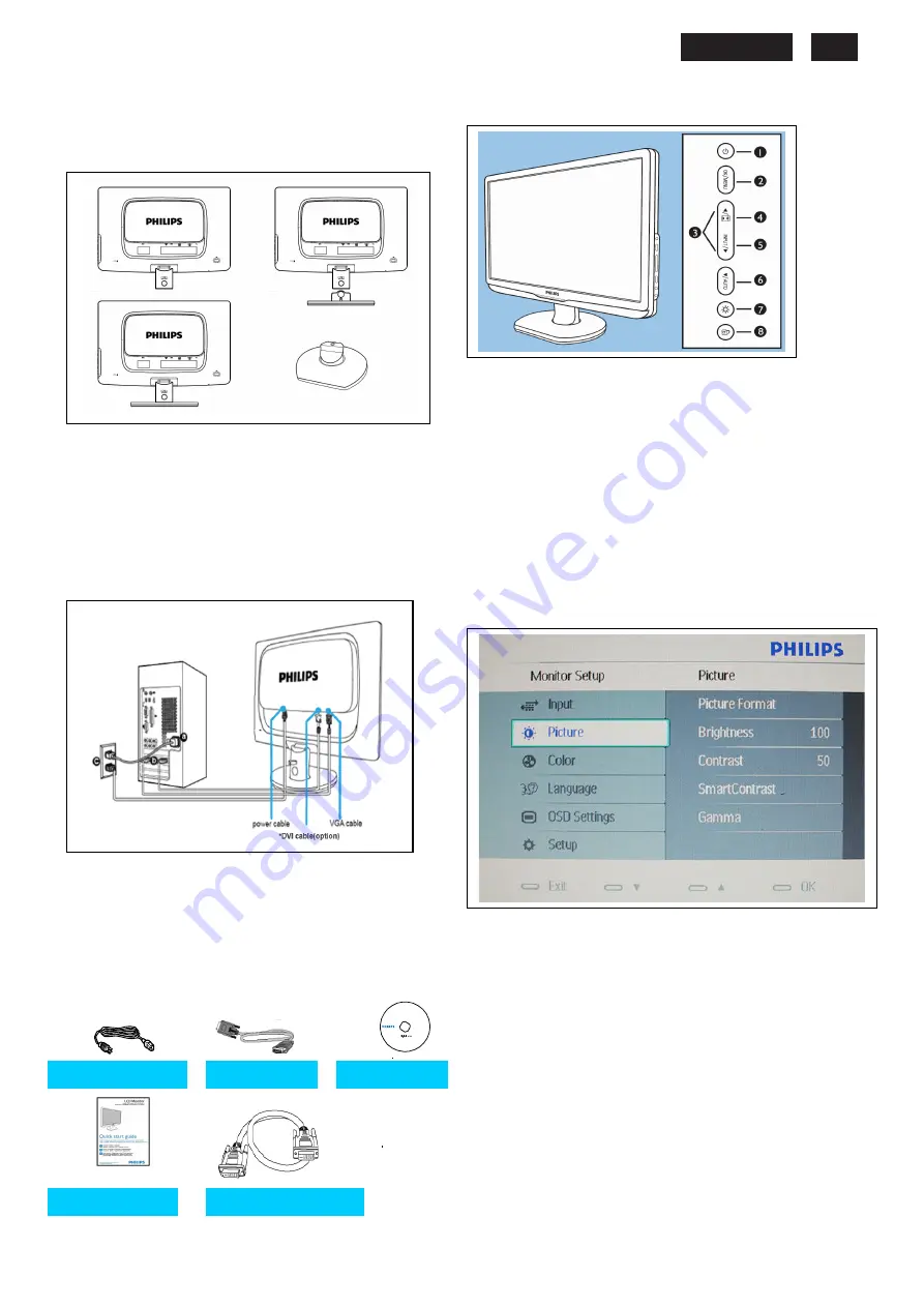
Connection to PC
(Package)
1. Connection to PC
Please follow the steps to connect your LCD Monitor to
PC.
a. Assembly LCD Monitor with base
b. Connect to PC
(1) Turn off your computer and unplug its power cable.
(2) Connect the monitor signal cable to the video
connector on the back of your computer.
(3)
Connect the audio cable to the audio port of your
computer
(4)
Plug the power cord of your computer and your
monitor
(5)
Turn on your computer and monitor. If the monitor
displays an image, installation is complete
Port definition:
(1)
VGA input
(2) DVI input
(3)
AC power input
(4)Kensington anti-thief lock
For best performance, use your Analog input and
ensure that your disolay settings are set at
1920*1080@60Hz
c. Accessory Pack
2. Function key definition
(1) To switch monitor's power On and Off
(2) To access the OSD menu.
(3) To adjust the OSD menu
(4)Change to 4:3 display
(5) To change the signal input source
(6) Automatically adjust the horizontal position, vertical position, phase
and clock settings / Return to previous OSD level
(7) To adjust volume of the display
(8) SmartImage. There are five modes to be selected: Office Work,
Image Viewing, Entertainment, Economy, and Off
3. Description of the On Screen Display
On-Screen Display(OSD) is a feature in all Philips LCD monitors. It
allows and end user to adjust screen performance or select functions
of the monitors directly through an on-screen instruction window. A
user friendly on screen display interface is shown as below:
*DVI Input ( available for selective models )
Basic and simple instruction on the control keys
According to the above OSD structure, users can
press
UP
or
DOWN
buttons to move the cursor,
press
MENU
button to confirm the choice or change
press
UP
or
DOWN
button to adjust the value
press
MENU
button to save the changes
press
AUTO
button to automatically adjust the horizontal position,
vertical position,phase and clock setting
Power cord
VGA cable
EDFU CD
Quick start
guide guide
DVI cabel (option)
guide
Содержание 231E1HSB
Страница 12: ...231E1 LCD 12 Wiring diagram ME ...
Страница 23: ...231E LCD 23 220EW9 LCD 23 Schematic Diagram Scaler Board Power ...
Страница 24: ...231E1 LCD 24 Schematic Diagram VGA Input ...
Страница 25: ...231E LCD 25 220EW9 LCD 25 Schematic Diagram DVI Input ...
Страница 26: ...231E1 LCD 26 Schematic Diagram Scaler Board Scaler ...
Страница 27: ...231E LCD 27 220EW9 LCD 27 Schematic Diagram Power Board ...
Страница 28: ...231E1 LCD 28 Layout side View Scaler Board 1 ...
Страница 30: ...231E1 LCD 30 Layout side View Power Board ...
Страница 31: ...231E LCD 31 220EW9 LCD 31 Exploded View ...
Страница 39: ...231E LCD 39 General Trouble Shooting Guide ...
Страница 41: ...231E LCD 41 General Trouble Shooting Guide Continued 1 ...
Страница 43: ...231E LCD 43 General Trouble Shooting Guide ...
Страница 44: ...231E1 LCD 44 General Trouble Shooting Guide 5 ...
Страница 45: ...231E LCD 45 General Trouble Shooting Guide 6 ...
Страница 46: ...231E1 LCD 46 General Trouble Shooting Guide 7 ...
Страница 47: ...231E LCD 47 General Trouble Shooting Guide 8 ...
Страница 48: ...231E1 LCD 48 General Trouble Shooting Guide 9 ...
Страница 49: ...231E LCD 49 General Trouble Shooting Guide 10 ...
Страница 50: ...231E1 LCD 50 General Trouble Shooting Guide 11 ...
Страница 51: ...231E LCD 51 General Trouble Shooting Guide 12 ...
Страница 52: ...231E1 LCD 52 General Trouble Shooting Guide 13 ...
Страница 69: ...231E LCD 69 END ...


