


13
1063_0_Product_Manual - October 27, 2010 2:54 PM
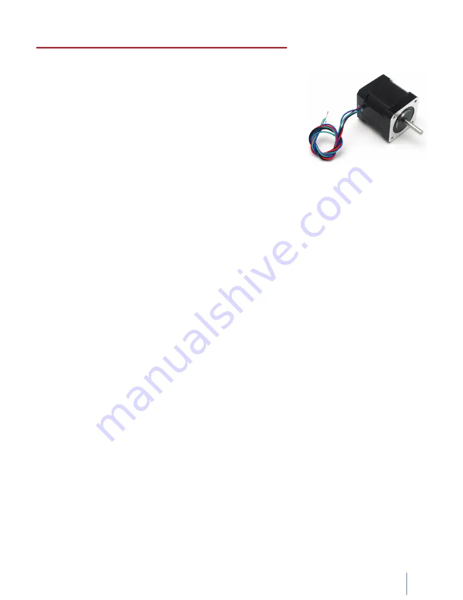
Introduction to Stepper Motors
Stepper motors are broadly available motors commonly used for positioning.
DC Motors are controlled by simply applying power which sends them blindly
spinning. Steppers Motors are controlled in a series of discrete steps, allowing
them to be sent to a very precise position. By repeating the set of steps
over and over, the motor can be made to rotate while your system tracks the
position.
Some steppers will require hundreds of steps to do a full rotation, while others,
like the air core motor, can do a full rotation with only 4 steps.
The vast majority of steppers are built using two coils of wire, whose magnetism
pulls or repels a rotating magnet attached to an exposed shaft. Depending on
how these two coils are available to wire up, we get 4, 5, 6 or 8 wire stepper motors.
How does the 1063 control Stepper Motors?
The 1063 can be used to control 4, 6, or 8 wire bipolar stepper motors.
The PhidgetStepper Bipolar is most effective when used with stepper motors designed to be driven with a chopper
drive stepper controller. These motors are often large, with a rectangular industrial appearance. The specifications
of these motors are often confusing and may seem contradictory. The relationship between maximum motor
voltage, coil resistance, maximum current, and power supply voltage is not intuitive. Under most circumstances, the
1063 controls these parameters automatically.
The 1063 PhidgetStepper is different from many familiar stepper controllers. Many stepper controllers rely on
the resistance of the coils of wire inside the stepper motor to control the amount of current. In fact, the 1062
PhidgetStepper uses this simpler (and cheaper) method. The 1063 uses high speed electronics and the magnetic
field within the motor coils to control the current, effectively reducing the voltage to what is required for your motor.
The PhidgetStepper Bipolar can be used with smaller steppers that are designed to limit current through their own
coil resistance. Special attention must be paid to the CurrentLimit property set in software.
The PhidgetStepper Bipolar uses constant current control to control the power flowing through the motor coils.
The constant current is implemented by allowing the current in the coil to ramp up until it reaches a setpoint, then
turning off the coil, allowing the current to recirculate and gradually reduce. The coils being rapidly turned on/off
produces a slightly audible whine.
At low speeds, less than 1024 1/16th steps per second, the 1063 uses a microstepping scheme to allow precise
control of the current to each coil, and therefore the position of the stepper. It’s important to note that many
steppers are not designed to be microstepped precisely, and will not accurately produce the expected angle.
At higher speeds, the 1063 switches to a full stepping mode. The 1063 will automatically switch back to
microstepping when approaching the target position.
How to connect your Stepper to the 1063
Introduction
Bipolar Steppers motors are available in 4, 6 or 8 wire configurations. Driving a motor in the Bipolar Configuration
produces maximum torque. The word Bipolar means that the controlling electronics have to be able to produce a
current flow in either direction in each coil, to produce magnetic fields in opposite directions.
Technical Section