Phase Technologies HASE PERFECT DPC-20 Скачать руководство пользователя страница 14

14

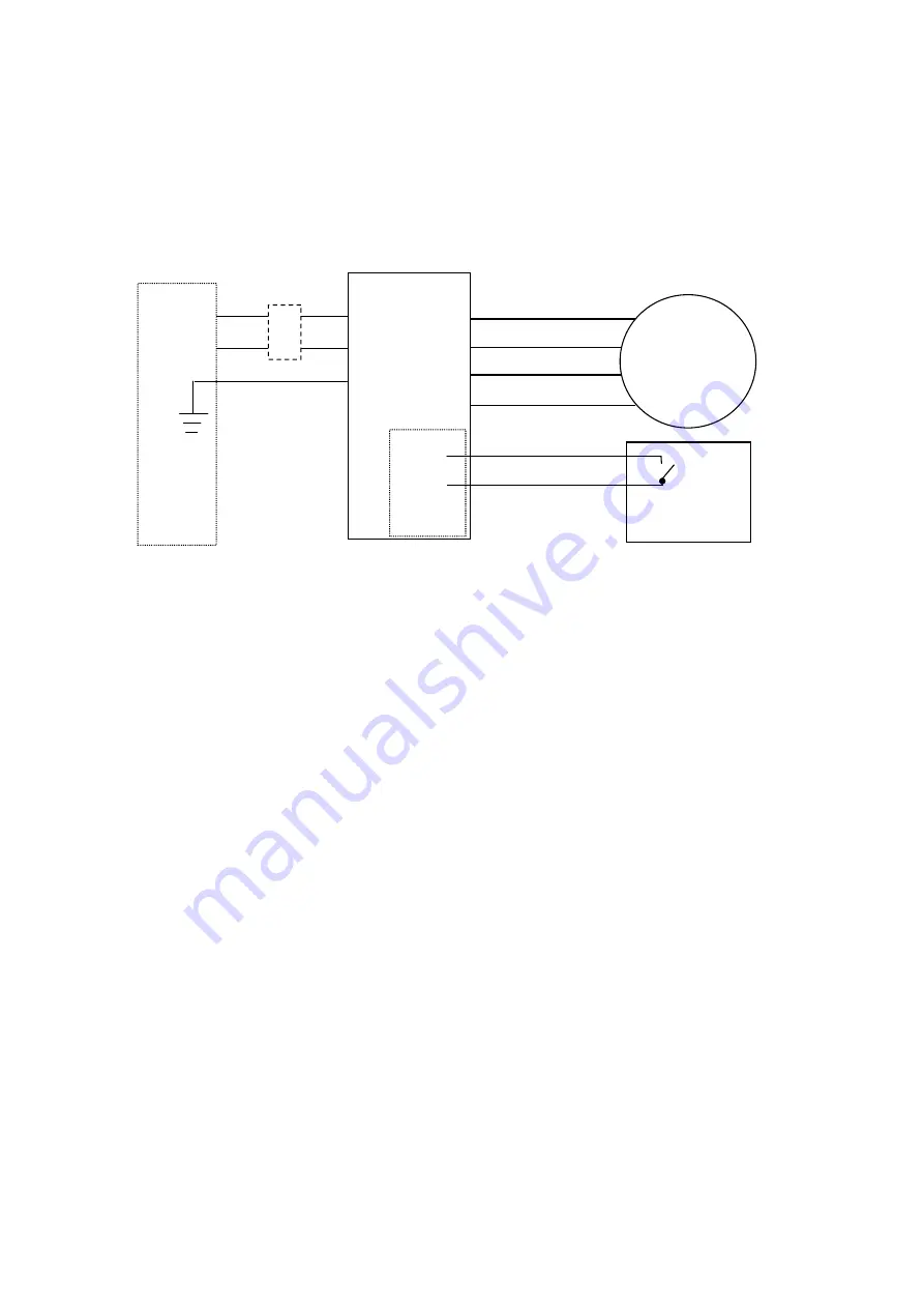
motor starter configuration, with the addition of an ON/OFF control switching
mechanism. The configuration used to power an individual motor with control
circuit is illustrated below:

The following points should be considered when wiring Phase Perfect

to power

a motor controlled by a remote switch such as a level or pressure switch:

1. Verify that no power is provided to Phase Perfect

.

2. Remove the front panel to gain access to the wiring terminals. See

section 2.2.1, “Wiring to Phase Perfect

Terminals,” for a drawing

illustrating the components found under the access panel.

3. Remove the factory installed jumper between the control terminal

contacts A and B. Wire the remote pressure switch, level switch, or
other control switch to control terminals A and B.

When the remote

switch is closed the overload relay will be enabled and power will
be provided to the motor or load after an approximately five to
eight second delay.

The control switch should have a minimum

rating of 240 VAC, 0.5 amp. A 3 amp fuse located just below the
printed circuit board protects the remote switch circuit.

4. Wire Phase Perfect

to the motor as illustrated above. Three-phase

output power wire connections are made to the T1, T2, and T3 output
terminals, and secured with the terminal block screws.

5. Set the motor protection unit to the desired settings:

c. Adjust the trip current to the appropriate current for the motor load

being powered. The trip rating is 120% of the dial setting.

d. Set the overload relay to auto or manual reset as desired. For auto

reset push and turn the reset button clockwise to the Auto
position. The button will remain depressed.

DANGER: In this

position the relay will reset automatically approximately two
minutes after tripping, providing power to the load without
warning.

For manual reset push and turn the reset button to the

POWER OUTLET OR

BREAKER PANEL

PHASE

PERFECT

240 VAC
0.5 AMP

C T
O E
N R
T M
R I
O N
L A

L

CLOSED
FOR ON

CONTROL SWITCH

MOTOR

T1

T2

T3

GND

A

B

C

L1

L2

GND

FUSIBLE

DISCONNECT

Содержание HASE PERFECT DPC-20

Страница 1: ...1 PHASE PERFECT DIGITAL PHASE CONVERTERS OPERATION INSTALLATION MANUAL PHASE TECHNOLOGIES LLC ...

Страница 2: ...2 DANGER HIGH VOLTAGE Electric shock could result in death or injury Please consult qualified personnel for installation DANGER Risk of Electric Shock Please wait 30 minutes before servicing ...

Страница 3: ...power factor correction Phase Perfect operates at near unity power factor 99 Phase Perfect output is three phase sinusoidal with virtually no added harmonic content Phase Perfect output voltages are balanced to 1 Phase Perfect will operate in the voltage range from 187 to 260 VAC Phase Perfect can be configured for use as either a Power Supply or a Motor Starter In the Power Supply configuration P...

Страница 4: ... the responsibility of the original purchaser Return transportation is provided by Phase Technologies Exclusions of the Warranty This warranty does not cover any of the following accident misuse fire flood and other acts of God nor any contingencies beyond the control of Phase Technologies LLC including water damage incorrect line voltage improper installation missing or altered serial numbers and...

Страница 5: ...DERATIONS 2 2 2 TYPICAL SYSTEM CONFIGURATIONS 2 2 2 1 MOTOR STARTER CONFIGURATION 2 2 2 2 MOTOR STARTER WITH REMOTE ON OFF CONTROL 2 2 2 3 POWER SUPPLY CONFIGURATION 3 OPERATION 3 1 ON OFF FUNCTION 3 2 STATUS LIGHTS 4 OVERLOAD RELAY INFORMATION 5 TROUBLESHOOTING 5 1 GENERAL TROUBLESHOOTING TIPS 5 2 TROUBLESHOOTING WITH STATUS LIGHTS 6 FEATURES AND SPECIFICATIONS 6 1 FEATURES 6 2 SPECIFICATIONS ...

Страница 6: ...affect the operation of the equipment If the connected load has a neutral connection and requires wye configured power the output of the phase converter must be passed through a delta to wye isolation transformer before connection to the load Unlike other converter technologies Phase Perfect actively monitors input and output currents and voltages to maintain power balance under all load condition...

Страница 7: ...er to provide proper ventilation do not obstruct the open space under and around the enclosure Make sure air intake and exhaust openings are not obstructed If the unit is mounted in a cabinet or shed make certain there is adequate ventilation to provide cooling for the unit 2 2 ELECTRICAL INSTALLATION Electrical connections to the Phase Perfect are made behind the front panel of the enclosure as d...

Страница 8: ...e enclosure to gain access to the wiring panel The wiring panel and key components of Model DPC 20 are illustrated below INPUT POWER GROUNDING LUG INPUT POWER TERMINAL BLOCK CONTROL TERMINALS OUTPUT POWER GROUNDING LUG OUTPUT WIRING TERMINAL BLOCK FACTORY INSTALLED JUMPER ...

Страница 9: ...arter option allows Phase Perfect to start and protect single motor loads Models DPC A10 DPC 20 and DPC 30 are equipped with a remote reset button on the front of the enclosure so that the overload relay can be reset without opening the enclosure 2 2 1 1 GENERAL WIRING CONSIDERATIONS Installations must comply with all national and local electrical code requirements General Wiring Considerations In...

Страница 10: ... by a qualified electrician into a 208V or 240 V circuit with adequate current carrying capacity and the appropriate sized breaker Branch circuit protection to the phase converter should be provided by either an appropriate size 2 pole linked circuit breaker Circuit breaker size for each model Phase Perfect is listed in Table 1 Table 1 Model DPC A10 DPC 20 DPC 30 Input Terminals Tightening torque ...

Страница 11: ...t from any two legs If the unit is connected incorrectly the generated phase to ground voltage will be 240 V causing the unit to shutdown and the yellow status light to flash In this event reverse the L1 and L2 input connections PHASE PERFECT 120 V 120 V 120 V 208 V GND L1 L2 POWER OUTLET OR BREAKER PANEL Three phase 240 120 V Delta CAUTION In rare situations single phase 240 V input power is take...

Страница 12: ...nd capacitive loads can be safely powered by Phase Perfect Three typical Phase Perfect installations are diagrammed and explained below 1 a motor starter configuration for use with a single motor load 2 a pump configuration in which a pressure or level switch automatically controls power to the pump and 3 a power supply configuration for use in powering multiple three phase loads 2 2 2 1 MOTOR STA...

Страница 13: ...n the reset button to the manual position In this position pushing the button in resets the overload relay Additional information on the motor protection unit is provided in Section 4 Motor Protection Unit 6 Wire power into Phase Perfect from an appropriate 208 V or 240 V circuit See section 2 2 1 2 Input Wiring Considerations for additional information 7 Re attach the front panel 8 Provide power ...

Страница 14: ...ve to eight second delay The control switch should have a minimum rating of 240 VAC 0 5 amp A 3 amp fuse located just below the printed circuit board protects the remote switch circuit 4 Wire Phase Perfect to the motor as illustrated above Three phase output power wire connections are made to the T1 T2 and T3 output terminals and secured with the terminal block screws 5 Set the motor protection un...

Страница 15: ... 2 2 3 POWER SUPPLY CONFIGURATION Phase Perfect can be configured as a power supply to provide three phase power to multiple loads of any type including inductive resistive and capacitive loads If the Phase Perfect unit includes the optional Motor Starter feature the jumper on the control terminals should be moved to connect B and C terminals This will disable the motor overload relay Separate pro...

Страница 16: ...on 2 2 1 2 Input Wiring Considerations for additional information 7 Re attach the front panel 8 Provide power to Phase Perfect from the fusible disconnect Power will be available to the load circuits after an approximately five to eight second delay Check each motor for correct rotation If the motor rotation is incorrect reverse any two of the three output power leads T1 T2 and T3 at the output of...

Страница 17: ...dition to the basic status light functions indicated above flashing status lights and combinations of status lights are designed to indicate and help troubleshoot a wide range of potential problems A complete listing of status light indications is provided in Section 5 2 Troubleshooting with Status Lights 4 SOLID STATE OVERLOAD RELAY INFORMATION Phase Perfect is available with an optional solid ov...

Страница 18: ...such as a pumping shed Manual reset is typically used when the Phase Perfect unit is readily accessible such as in a machine shop a For auto reset push and turn the reset button clockwise to the Auto position The button will remain in the IN position The unit will reset automatically approximately two minutes after tripping ATTENTION Do not use the automatic reset mode in applications where unexpe...

Страница 19: ...s 5 1 GENERAL TROUBLESHOOTING TIPS After the system is fully wired turn the Phase Perfect unit ON with the fusible disconnect If the unit fails to turn ON and all status lights are OFF check the following 1 Verify that the appropriate circuit breaker in the building s electrical distribution box is set ON and is properly sized 2 Check the control circuit fuse located on the panel just below the pr...

Страница 20: ...voltage Contact utility 3 Flashing Green and Flashing Yellow Output current too high Short between T3 T1 or T2 Excessive load Eliminate short Ensure steady state current is within ratings Higher current is OK for momentary load startup 2 Steady Green and Yellow Or Steady Red High DC bus voltage High utility line voltage Short between T1 T2 or T3 Ensure input line voltage between L1 and L2 is below...

Страница 21: ...6 amps 64 amps 96 amps Momentary overload current 4 seconds 150 amps 280 amps 400 amps Rated HP 10 20 30 Output voltage Equal to input voltage Service factor 1 2 1 2 1 2 Enclosure Type 1 indoor or 3R rain proof Type 1 indoor or 3R rain proof Type 1 indoor or 3R rain proof Weight 123 lb 230 lb 330 lb Dimensions H x W x D in Type 1 indoor Type 3R rainproof 22 x 21 x 12 27 x 21 x 12 30 x 27 x 15 34 x...

Отзывы: