Pfaff EXPRESSION 2014 Скачать руководство пользователя страница 30

28

6. Adjustment of presser foot height

Requirement:

With the presser bar lifter raised there must be a clearance of 8 mm between the needle plate and the

sole of the zigzag foot.

Check:

Raise the presser bar lifter.

Fit the zigzag foot.

Lower the feed dog.

Fully raise the presser bar lifter and hold it in this position.

Insert the presser foot gauge (63-114 690-39) from behind under the zigzag foot and into the cutout of

the needle plate (fig. 20).

Lower the presser bar lifter to its normal position again.

The zigzag foot must rest parallel and without play on the presser foot gauge.

However the presser foot gauge must not lift the zigzag foot.

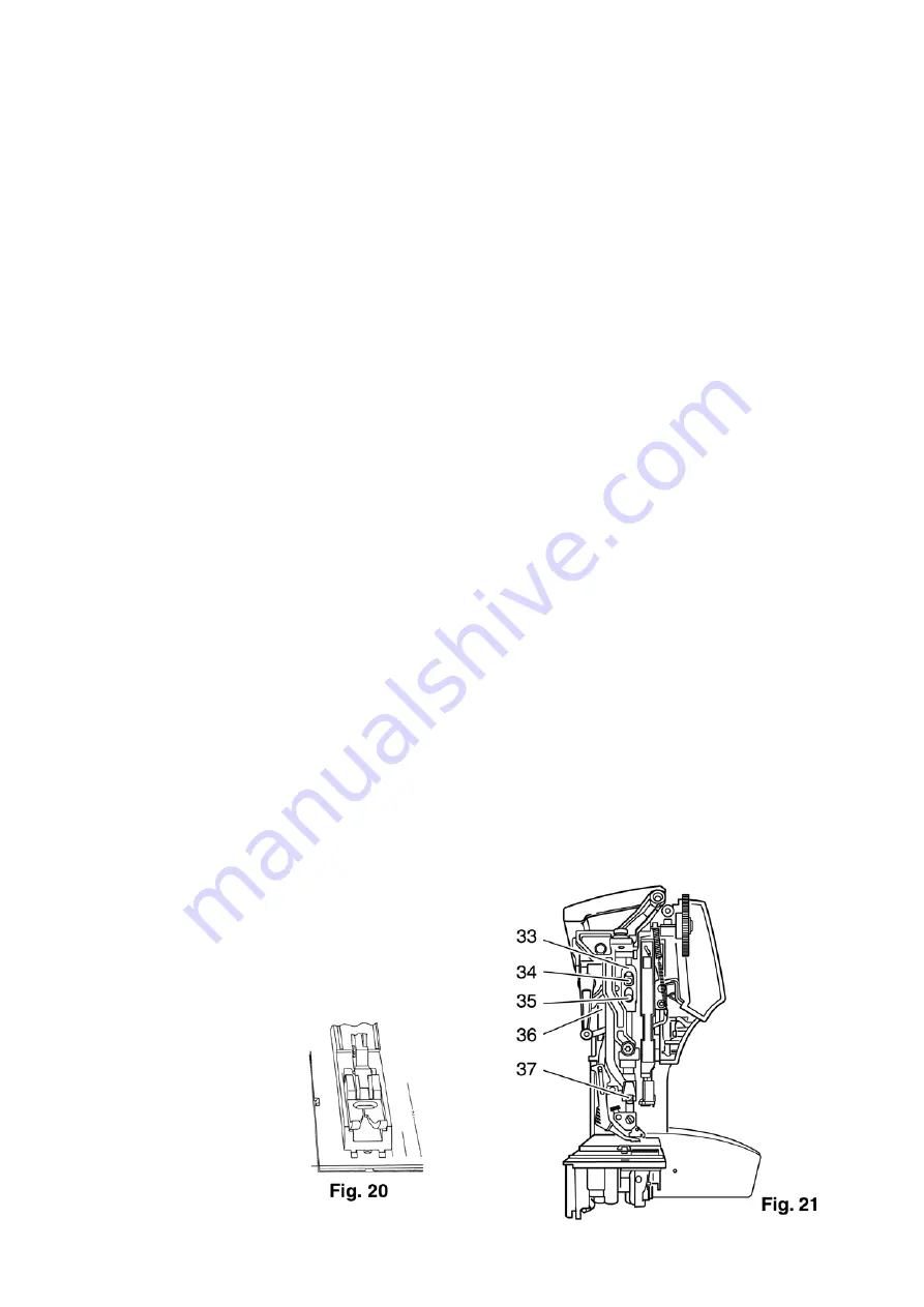
the needle thread tension must be without play (fig. 21).

Adjustment:

Loosen the three screws 34, 35 and 37 (fig. 21).

Turn the zigzag foot with the presser bar lifter raised until it is parallel with the sides of the presser foot

gauge.

Use a screwdriver to press presser bar guide 36 firmly down.

At the same time firmly tighten screw 35.

Cross-check:

Press the presser bar lifter further upward and release it again.

The zigzag foot must rest parallel and without play on the presser foot gauge.

Needle thread tension release lever 33 must be without play. The presser bar lifter must be in its raised

position.

Note:

The two screws 34 and 37 are not tightened until later

when the top feed height is set.

Содержание EXPRESSION 2014

Страница 1: ...Service Manual 1st edition November 2002 expression 2014 2024 2034 2044 german engineering...

Страница 2: ...Leerseite...

Страница 3: ...position finger 43 Stitching off 15 Adjustment of needle threader 44 16 Adjustment of bobbin winder stop 45 17 Adjustment of bobbin thread tension 46 18 Adjustment of needle thread tension 46 19 Adjus...

Страница 4: ...needle threader 92 41 Self test foreword 93 42 Self test model 2014 and 2024 94 43 Table for self test model 2034 97 44 Table for self test model 2044 100 45 Fault table for electrical parts 2044 103...

Страница 5: ...ts of technical devices The required electrical tests for appliances are set forth in Para 4 of the Regulations for Repair Modification and Testing of Used Electrical Devices VDE 0701 edition 05 93 Af...

Страница 6: ...soft cloth with a neutral cleansing agent for plastic materials Please note Do not use any insecticides or chemical products such as petrol gas or thin chemicals for cleaning the housing Display If ne...

Страница 7: ...rogram When machine is blocked the motor is switched off automatically after 1 2 secs Followed by approx 4 secs interruption before sewing process can be continued Machine voltage change over 115 230...

Страница 8: ...Wing needle Suffix Wing Twin hem stitching needle Suffix Zwi Ho Long needle eye Suffix N Stretch needle Suffix PS Denim needle Suffix J Possible needle points Small ball point Suffix SES Medium ball p...

Страница 9: ...l motor control with 950 r p m max speed Approx 100 950 stitches per minute Several pattern dependent reduced speeds in addition Numerical LCD with graphics and a white background Built in test progra...

Страница 10: ...die cast aluminium Machine weight without carrying case 8 3 kg Needle system 130 705 H Additional needle system classifications Twin needle Suffix Zwi Wing needle Suffix Wing Twin hem stitching needl...

Страница 11: ...plug and the socket on the machine Remove the needle and the presser foot shoe Remove the detachable work support Remove the top cover Unscrew and remove the two torx screws of the housing insert Rem...

Страница 12: ...te face plate together with the sewing lamp and cable fig 3 Remove the carrying handle Unscrew and remove the three fastening screws on the baseplate Tilt the baseplate toward the front Remove 12 wire...

Страница 13: ...ver fig 5 Put the feed drop mechanism in its normal working position Using a small screwdriver disengage both feed regulators 6 Open the cable clip Remove connection plug 7 from the circuit board fig...

Страница 14: ...12 Remove the needle plate Unscrew and remove both fastening screws 8 fig 7 Remove the free arm cover Loosen screw 9 on the stand cover fig 8 Remove the stand cover...

Страница 15: ...g screws 10 and 11 on the rear housing shell fig 9 and 10 Open the catch connections on the inside of the arm by pressing with your thumb against the points indicated by the arrows fig 11 Remove the r...

Страница 16: ...Remove the five connection plugs 12 13 14 15 and 16 from the circuit board fig 12 Loosen fastening screws 17 and 18 fig 13 as well as fastening screw 19 fig 14 Remove the front housing shell carefull...

Страница 17: ...15 Remove buttonhole sensor s cable guide 20 fig 15 Remove the complete buttonhole sensor with the spring...

Страница 18: ...16 Notes...

Страница 19: ...has no play in its rotating direction but it must be possible to turn the machine easily Adjustment Loosen screw 1 fig 1 Re position tensioning roller 2 with a screwdriver accordingly Tighten screw 1...

Страница 20: ...ical pins 12 and 13 sideways without play until the feed dog is positioned in the middle of the feed slot Tighten screw 10 The pressure of the right cylindrical pin must be 1 kg Tighten screw 11 Remov...

Страница 21: ...20 sideways until link 7 and connecting rod 19 still have some play and move easily Tighten screw 4 Attach both springs 3 and 9 Cross check The feed dog must now be positioned in the exact middle of t...

Страница 22: ...and 13 sideways without play until the feed dog is positioned in the middle of the feed slot Tighten screw 10 The pressure of the right cylindrical pin must be 1 kg Tighten screw 11 Remove the needle...

Страница 23: ...e slide block moves easily and without play Push link 7 complete with feed regulator 6 to the right onto the connecting bar pin Push feed regulator 6 to the rear and then upward over feed eccentric 5...

Страница 24: ...d c it must be possible to insert the two pins of pin gauge 63 114 690 09 simultaneously in the holes of the feeding eccentric and the stud fig 9 Check Remove the needle Turn the handwheel to set the...

Страница 25: ...til the needle bar has moved upwards by 2 mm and the clamp is in contact with the spacer fig 8 Turn the long drive shaft 28 in sewing direction until it is possible to insert the pin gauge in both hol...

Страница 26: ...set feeler lever 30 on the feed dog fig 12 Turn the handwheel until pointer 31 has moved up to its highest position The pointer must now point exactly at mark 0 9 Adjustment Leave the adjustment gauge...

Страница 27: ...25...

Страница 28: ...ove the needle Remove the presser foot Switch on the master switch Set stitch pattern 01 and stitch length to approx 0 5 mm Set adjustment gauge 63 114 690 23 on the needle plate so that feeler lever...

Страница 29: ...n turning control cam 32 until the stepping motor switches Tighten the fastening screw on control cam 32 whilst ensuring that the cams of the control cam are in the middle of the circuit board guides...

Страница 30: ...r foot gauge However the presser foot gauge must not lift the zigzag foot the needle thread tension must be without play fig 21 Adjustment Loosen the three screws 34 35 and 37 fig 21 Turn the zigzag f...

Страница 31: ...until the rising feed dog is flush with the needle plate surface Lower the presser bar lifter Carry out a visual check Adjustment Loosen screw 39 fig 23 Raise the presser bar lifter until the top feed...

Страница 32: ...d into the cutouts of the needle plate Lower the presser bar to its normal raised position Press the top feed lightly downward Check that the top feed foot rests only lightly on the presser foot gauge...

Страница 33: ...31 Cross check Turn the handwheel and check for clearance of 0 2 mm...

Страница 34: ...ct stitch pattern 01 for straight stitch Turn the handwheel until the needle is in the needle hole Carry out a visual check fig 26 Select stitch program 03 and a zigzag width of 6 mm Turn the handwhee...

Страница 35: ...33...

Страница 36: ...ther the looper point must enter the thread loop widen it and guide it around the bobbin Needle bar height The needle bar height must be set in such a way that the sewing hook point can easily enter t...

Страница 37: ...100 needle is positioned exactly in the middle of the needle hole as seen in feeding direction while the point of an Nm 80 needle is positioned slightly closer to the back edge of the hole Check Inser...

Страница 38: ...ate Remove the face plate Remove Benzing circlip 51 on the needle bar frame fig 30 Disengage the connecting rod and the needle bar frame Move the needle bar frame to the left and to the right Importan...

Страница 39: ...37...

Страница 40: ...rn the handwheel until the hook point is opposite the center line of the needle Check the distance between hook point and needle scarf Check the axial play of hook 52 to hook shaft bush 54 fig 34 Adju...

Страница 41: ...wing hook point and the bottom of the needle scarf 11a Adjustment of bevel gears Requirement The bevel gears must move freely and without play Adjustment Push the bevel gear with the lifting eccentric...

Страница 42: ...y on the feeler gauge repeat this procedure Remove the 2 2 mm feeler gauge Turn the handwheel in sewing direction until the needle rise clamp is in contact with the spacer fig 36 By this means the nee...

Страница 43: ...41...

Страница 44: ...lower edge of the sewing hook point must be 0 5 mm at the widest left zigzag penetration fig 39 Check Select stitch program 03 and the widest zigzag width of 6 mm Turn the handwheel until the needle...

Страница 45: ...1 Check It must be possible to insert the clearance gauge 61 111 621 15 with ease but without play between the position finger and the bottom of the groove in the bobbin case base Adjustment Loosen sc...

Страница 46: ...ig 43 Push the complete threader bar frame 67 either upwards or downwards until prong 62 has the same clearance to the top and bottom edge of the needle eye fig 42 Tighten allen screw 66 in this posit...

Страница 47: ...ached a level of 1 mm below the bobbin rim Check Wind a bobbin and check that the winder stops as required Adjustment Loosen screw 68 fig 45 Position stop 69 to the left for less thread and to right f...

Страница 48: ...rest evenly and parallel on the bobbin case Adjustment Loosen the knurled screw a little and turn it in again until a resistance is felt when the thread is pulled off Check Carry out as described unde...

Страница 49: ...ght stitch and set the stitch length at 2 5 Sew with straight stitch Adjustment First turn milled nut 57 fully to the left fig 51 Set zigzag stitch 03 stitch width 6 0 and stitch length 2 0 Sew with z...

Страница 50: ...the lower edge of the needle eye enters the fabric Check Select stitch pattern for straight stitch Set the stitch length at 6 0 Place two pieces of fabric under the sewing foot Sew a few of stitches T...

Страница 51: ...49 Notes...

Страница 52: ...in direction A using a screwdriver as shown in fig 58 If a rhombus was sewn as seen in fig 54 turn the adjusting eccentric just 2 4 degrees in direction B using a screwdriver as shown in fig 58 Cross...

Страница 53: ...ifficult fabrics are used buttonholes utility stitches or fancy stitches may be sewn with shifts in the pattern design To correct this the customer can adjust the balance On top of that the length of...

Страница 54: ...4 If a rhombus was sewn as seen in fig 61 turn adjusting eccentric just 2 4 degrees in direction B as shown in fig 64 Cross check Sew adjusting program 95 and check On model 2034 select adjusting prog...

Страница 55: ...ifficult fabrics are used buttonholes utility stitches or fancy stitches may be sewn with shifts in the pattern design To correct this the customer can adjust the balance On top of that the length of...

Страница 56: ...f the customer has special requirements these should appear on a separate sewing sample The following is a sewing sample from the PFAFF expression 2044 Stitch program No Stitch width Stitch length Pre...

Страница 57: ...te with pressure piece 77 and the three tension discs 78 79 and 80 Fitting Insert tension stud 76 with the three tension discs 78 79 and 90 and the pressure piece 77 Cement the tension stud into the m...

Страница 58: ...washer 89 fig 67 Fitting the handwheel Push spring washer 89 onto the arm shaft Insert torsion spring 88 into bushing 87 Attach bushing 87 together with torsion spring 88 onto the arm shaft Press spr...

Страница 59: ...57...

Страница 60: ...ith sewing hook gib into the sewing hook fig 74 Fasten the sewing hook gib from behind with three screws with springs fig 69 Screw on and adjust the bobbin case position finger 26 Cleaning and oiling...

Страница 61: ...59...

Страница 62: ...er right calotte bearing 92 as far as it will go Pull the flat toothed belt between calotte 95 and calotte bearing 92 Disconnect tension spring 96 on needle bar frame 44 fig 75 Remove lockwasher 51 on...

Страница 63: ...61...

Страница 64: ...ccording to section 1 Turn the handwheel until the fastening screw of the synchronizer control cam 32 faces downwards fig 79 At the same time pin 107 on the upper sprocket faces upwards Press needle b...

Страница 65: ...63...

Страница 66: ...0 870 136 01 with its cutout on the needle bar above the needle rise clamp Loosen the needle rise clamp and push the 2 mm feeler gauge upward against the spacer Tighten the milled screw on the needle...

Страница 67: ...e Mount the facing panel of the front housing panel Insert the housing insert and fasten with the torx screws Attach the top cover The following points must be checked and adjusted Section 17 Adjustme...

Страница 68: ...screw 60 of the bobbin case position finger 61 Remove the bobbin case position finger Turn the handwheel until the lobe of feed eccentric 5 is at the rear Unscrew and remove screw 4 and clamping plate...

Страница 69: ...67...

Страница 70: ...crew 57 on the surface of hook driving shaft 28 fig 83 Screw in dog point screw 108 into feed eccentric 5 or the hook driving shaft Note Dog point screw 108 must always protrude from feed eccentric 5...

Страница 71: ...cable Insert the buttonhole sensor Attach the free arm cover and secure with both fastening screws 5 Bring the feed dog lowering mechanism to its normal working position Engage both feed regulators 6...

Страница 72: ...ve wire flat cable 3 as well as the connection plug of motor cable 4 from the circuit board fig 84 Fitting Set the new base plate complete against the machine Mount both connection plugs 3 and 4 on th...

Страница 73: ...71...

Страница 74: ...lding cover Unscrew and remove both torx screws of the housing insert Remove the housing insert Raise both lugs 1 slightly and remove the facing panel of the front housing panel in the direction of th...

Страница 75: ...onto the front housing panel making sure that both lugs 1 lock into place fig 87 Attach the housing insert and secure with both torx screws Attach the folding cover After a running in time of 10 15 m...

Страница 76: ...Unscrew and remove both torx screws of the housing insert Remove the housing insert Raise both lugs 1 slightly and remove the facing panel of the front housing panel in the direction of the arrow fig...

Страница 77: ...make sure that both lugs 1 lock fully into place fig 91 Attach the housing insert and secure with both torx screws Attach the folding cover Carry out a functional test for all keys After a running in...

Страница 78: ...ing according to the service manual Remove connection plug 113 from the circuit board fig 92 Unscrew and remove the five fastening screws 121 fig 93 Remove the complete circuit board together with the...

Страница 79: ...113 on the circuit board on the front housing panel fig 95 Fit the complete housing according to the service manual Carry out a functional test for all keys After a running in time of 10 15 min check...

Страница 80: ...he housing with fastening screw 123 using the torx offset screwdriver TX 15 fig 97 Make sure that the circuit board is positioned as such so that the cams of control cam 32 are positio ned in the midd...

Страница 81: ...79...

Страница 82: ...e housing to the right Remove both of the motor s power cables fig 102 Fitting Place flat toothed belt on the handwheel fig 101 Attach both power cables paying attention to the plus signs fig 102 Inse...

Страница 83: ...81...

Страница 84: ...ght guide pin Place both cables in the respective guide grooves Place contact spring 136 on the guide pin in the larger right section of pedal 130 Push pressure spring 132 onto the same guide pin Turn...

Страница 85: ...83...

Страница 86: ...ner in the direction of the arm shaft Remove the zigzag stepping motor to the front out of the housing Fitting Install zigzag stepping motor 46 in the housing Pull power cable downward Insert and tigh...

Страница 87: ...85...

Страница 88: ...slide block 8 with spring onto the bolt and set it in the guide slot in the correct curve radius Check that the slide block moves freely but without play or binding in the guide slot Push guide lever...

Страница 89: ...87...

Страница 90: ...rd fig 110 Remove the free arm cover from the housing to the left Remove connection plug 13 from the circuit board of the front housing panel and pull the cable downward fig 110 Remove cable guide 20...

Страница 91: ...ree fastening screws Mount the facing panel onto the front housing panel Insert the housing insert and secure with both torx screws Attach the folding cover Carry out an electrical safety test in acco...

Страница 92: ...cuit board of the front housing panel and pull the cable downward fig 113 Remove the free arm cover with the thread monitor from the housing to the left Fitting Install the new free arm cover with thr...

Страница 93: ...91...

Страница 94: ...hreader bar frame downward from threader bar 141 Fitting Push the new threader bar frame together with the needle threader on to the threader bar until bracket 139 clicks back into place Cross check I...

Страница 95: ...est is interrupted Generally an error in the corresponding test phase is indicated on the display with ER ER Error In some test steps an additional visual check must be carried out In some cases the o...

Страница 96: ...returns an error ER will appear on the display and the following tests will be skipped 4 KY keytest 0 sewing on buttons 1 straight stitch 2 stretch triplestraight stitch 3 zigzag stitch 4 elastic stit...

Страница 97: ...during the period of rea ding an error will be dis played 19 pattern mirror 7 PT Synchronizer test Turn handwheel two revolutions evenly to the front Pos up Stop up Pos down Intermediate pos Pos up T...

Страница 98: ...OK The program can only be exited by switching off machine If control is not actuated during the period of rea ding or the r p m are too low an error will be dis played The program stops after 12 sec...

Страница 99: ...faggoting stitch 9 buttonhole 10 pattern sequence 11 cursor left 12 cursor right 13 block monograms Actuate the key shown The next key to be actuated is shown If all keys have been recognized by the...

Страница 100: ...y no error must occur 6 Foot control foot control test Press foot control slowly as far as it will go twice from 0 85 Message OK or ERROR If control is not actuated the width display is empty If contr...

Страница 101: ...lay If control is not actuated the width display field is empty If the control is actuated the width display shows the standardized rpm actual reading e m f and the length display shows the standardiz...

Страница 102: ...oting stitch 9 buttonhole 10 pattern sequence 11 cursor left 12 cursor right 13 block monograms Actuate the key shown The next key to be actuated is shown If all keys have been recognized by the machi...

Страница 103: ...ntrol slowly as far as it will go twice from 0 85 Message OK or ERROR If control is not actuated the width display is empty If control is actuated the width display will show the standardized foot con...

Страница 104: ...ted during the period of rea ding or the r p m are too low a error will be dis played The program stops after 12 secs and the motor stops 11 Bobbin sensor Close free arm cover and actuate foot control...

Страница 105: ...base plate upper circuit board upper circuit board Figures do not light up or flicker on display field power pack base plate base circuit board upper circuit board Zigzag stepping motor runs continuo...

Страница 106: ...ar frame jams or is loose Zigzag movement of needle out of step straight stitch sewn zigzag stepping motor upper circuit board lower circuit board adjust synchronizer Take up lever top position and ne...

Страница 107: ...e the LCD shows the respective value 230 V 10 Touch contact field which is located a bit to the right just below the knob for the measuring range with your finger thus checking the ground lead of the...

Страница 108: ...rrent Milliampere mA Sewing machine plug remains in tester socket Use clamp to attach test lead of testing appliance M 5013 to presser bar Set knob for measuring range at 20 mA fig 118 Meter reading m...

Страница 109: ...107...

Страница 110: ...the indicated value although the machine does not bind the motor is defective and must be exchanged As to III If the insulation resistance drops below the required value the defective components must...

Страница 111: ...109 Notes...

Страница 112: ...z GmbH Stettiner Stra e 17 76356 Weingarten Printed in Germany Technische nderungen vorbehalten Subject to alterations in design Sous toute r serve de modifications techniques Salvo modificaciones t c...

Отзывы: