


45
Adjustment
1
.06.06
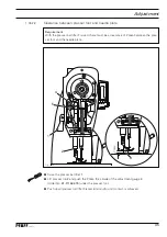
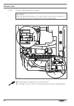
Cutting test
Requirement
1. The point of the thread catcher
2
must pick up the looper thread and the rear part of
the needle thread loop reliably.
2. When the cover plate
1
is removed, the threads must remain undamaged.
3. When the cover plate
1
is in position, the thread catcher
2
must move between the
knife
3
and the clamp springs
5
, during which the threads are properly cut and bound.
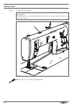
●
Place material under the presser foot and sew a few stitches.
●
Remove cover plate
1
.
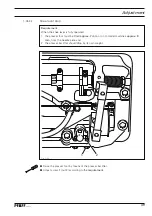
●
Position the needle as in
Chapter 1.06.04 Thread catcher interlock
.
●
Operate the cutting cylinder manually, checking
requirements 1
and
2
.
●
If necessary, readjust thread catcher
2
accordingly.
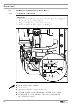
●
Screw on cover plate
1
.
●
Operate cutting cylinder again, checking
requirement 3
.
●
If necessary, carefully turn screw
4
according to
requirement 3
.
4
2
Fig. 1 - 38
1
3
1
5
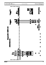
Consult the instruction manual for the drive for a description of the parameter
settings and a list of the parameters.