Pfaff 3834-14/11 Скачать руководство пользователя страница 103

Adjustment

13 - 36

13

.11

Service menu

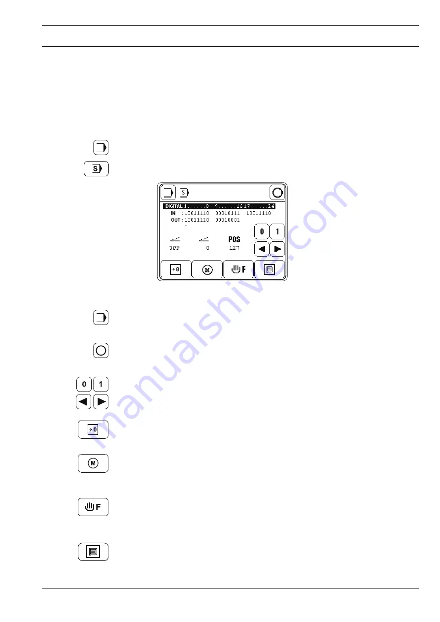
In the service menu information is displayed about the machine’s inputs and outputs, as well

as the values for both pedals and the balance wheel position.

In addition the following functions can also be carried out.

Switch on the machine.

Call up the input mode.

Call up the service menu.

Explanation of the functions

Input mode

Quit the service menu and call up the input mode.

Sewing mode

Quit the service menu and call up the sewing mode.

Set/reset outputs

Use the arrow functions to select the desired output and set "function 1" or reset "function

2".

Cold start

See 

Chapter 13.09 Carry out a cold start.

Motors

After this function has been called up, the stepping motors for roller presser and feed wheel

and for the sewing motor can be moved.

Balance wheel sequence

After selecting this function the stitch formation can be checked. The movement of the

stepping motors for the stitch length depends on the position of the balance wheel.

Control panel

See 

Chapter 9.13 Adjusting the control panel.

Содержание 3834-14/11

Страница 1: ...This instruction manual applies to machines from the following serial numbers onwards 2 733 153 INSTRUCTION MANUAL 3834 14 11 14 31 296 12 18 936 002 Betriebsanleitung engl 06 09...

Страница 2: ...cifications The reprinting copying or translation of PFAFF Instruction Manuals whether in whole or in part is only permitted with our previous authorization and with written reference to the source PF...

Страница 3: ...ls 6 1 7 Controls 7 1 7 01 On Off switch 7 1 7 02 Pedal 7 2 7 03 Machine head keys 7 1 7 04 Knee switch 7 3 7 05 Lever for raising the roller presser 7 3 7 06 Control panel 7 4 8 Mounting and commissi...

Страница 4: ...ng 10 1 10 01 Manual sewing 10 1 10 02 Sewing with fixed programs 10 3 10 03 Programmed sewing 10 5 10 03 01 Fullness adjustment 10 7 10 03 02 Selecting the garment size 10 7 10 03 03 Program interrup...

Страница 5: ...presser pressure 13 17 13 04 16 Locking the set value transmitter 13 18 13 04 17 Lubrication 13 19 13 04 18 Re engage safety coupling 13 20 13 05 Adjusting the thread trimmer 900 81 13 21 13 05 01 Re...

Страница 6: ...g sewing tools e g needle roller presser needle plate and bobbin when threading the machine when leaving the machine unattended and during maintenance work the machine is to be separated from the powe...

Страница 7: ...nnel is to be instructed as to the safety equipment of the machine and regarding safe work methods It is the duty of the user to only operate the machine in perfect running order It is the obligation...

Страница 8: ...y report to the person responsible any changes in the machine which may limit its safety 1 05 02 Specialist personnel Specialist personnel are persons with a specialist education in the fields of elec...

Страница 9: ...ings Objects can become trapped or be slung away Danger of injury Do not operate the machine without support 1 Danger due to top heavy sewing head Machine can tip over backwards when tilted Do not ope...

Страница 10: ...ds and reverse feeding feed wheel and driven puller This machine is used for sewing lockstitch seams in the clothing industry Any and all uses of this machine which have not been approved of by the ma...

Страница 11: ...V 10 50 60 Hz alternating voltage Max output 1 2 kVA Fuse protection 1 x 16 A delayed action Noise data Noise emission level at workplace with a sewing speed of 2700 spm LpA 80 dB A Noise measurement...

Страница 12: ...various plastics The electrical equipment consists of plastics and copper The machine is to be disposed of in accordance with the locally valid environmental protection regulations If necessary a spec...

Страница 13: ...use Always ensure that the machine is only transported upright 5 03 Disposal of the packaging The packaging of these machines consists of paper cardboard and VCE fiber The proper disposal of the packa...

Страница 14: ...this Instruction Manual certain tasks or important pieces of information are accentuated by symbols The symbols used have the following meanings Note information Cleaning care Lubrication greasing Se...

Страница 15: ...y turning On Off switch 1 1 7 02 Pedal 0 Neutral position 1 Sewing 2 Raise roller presser 3 Cut sewing thread and raise roller presser 1 4 Apply variable amount of fullness The current fullness is sho...

Страница 16: ...e roller presser feed stroke is reduced by pressing this key Key 3 The roller presser feed stroke is increased by pressing this key Diode 4 Diode 4 flashes when the pre selected number of stitches for...

Страница 17: ...ng lever 1 Fig 7 05 7 04 Knee switch By operating the knee switch 1 in the fixed programs and in programmed sewing it is possible to signal the end of the seam section To make it possible to switch to...

Страница 18: ...selected by pressing the appropriate position on the monitor By pressing the corresponding function this is carried out or switched on or off immediately or a further menu appears e g for entering a...

Страница 19: ...iciently sturdy including during all sewing operations 8 01 Mounting The necessary electricity supply must be available at the machine s location There must be a stable and horizontal surface and adeq...

Страница 20: ...2 from the accessories with screws 3 and 4 Do not operate the machine without tilt lock 1 Danger of crushing between sewing head and table top 1 2 3 4 8 01 03 Fitting the machine cover Slide the slots...

Страница 21: ...4 Remove the wedge from motor shaft 4 Attach angle bracket 5 with screws 6 Fit toothed belt wheel 7 to the motor shaft 4 so that the point of the screw is located in the groove of the motor shaft Scre...

Страница 22: ...ig 8 06 Connect all plugs as labelled to the control box 1 Screw the earth cable from the sewing head to earth point A Screw the earth cable 2 from the motor to earth point B Connect earth point C and...

Страница 23: ...ter the code number see Chapter 9 12 Entering altering the code number Turn the motor shaft by hand until the value 11 is under POS on the display Turn the balance wheel in sewing direction until the...

Страница 24: ...1 2 3 Fig 8 07 77 012 4 5 7 7 6 Move bearing plate 6 of the motor so that toothed belt 5 is stretched In this position tighten screws 7 Turn the balance wheel in sewing direction until the needle poin...

Страница 25: ...vents the machine starting when the main switch is on Fig 8 09 1 2 8 02 07 Checking the function of the start inhibitor Switch the machine on at the main switch and tilt back the sewing head The stop...

Страница 26: ...ne in particular the electric cables for any damage Have a qualified person check whether the motor can be driven with the existing power voltage If there are any differences the machine must definite...

Страница 27: ...g the needle Switch off the machine Danger of injury if the machine is started accidentally Only use needles from the system intended for the machine see Chapter 3 Specifications Raise the roller pres...

Страница 28: ...outside the sewing operation the drive for the roller presser Puller and the feed wheel should be switched off by pressing the wind the bob bin thread function This function is only available in the m...

Страница 29: ...bobbin case Insert bobbin case 2 Close the latch and close the post cap Fig 9 03 9 04 Threading the bobbin case Adjusting the bobbin thread tension Insert the bobbin into the bobbin case 1 Pass the t...

Страница 30: ...Preparation 9 4 9 05 Threading the needle thread Switch off the machine Danger of injury if the machine is started accidentally Thread the machine as shown in Fig 9 05 Fig 9 05...

Страница 31: ...e display from the numerical value e g 50 and on the bar graph display In the manual sewing mode and in the fixed programs 1 and 2 the thread tension can be changed directly In the programmed sewing m...

Страница 32: ...elect the desired program number Confirm the selection and quit the selection menu The type of sewing is stipulated with the selection of the program number see Chapter 10 Sewing Program number 0 Manu...

Страница 33: ...okes of the roller presser and feed wheel can be changed directly Switch on the machine Call up the stitch length input menu Change the feed strokes for roller presser and feed wheel individually or C...

Страница 34: ...ations with the fullness pedal left pedal Switch on the machine Call up the input mode Select parameter 107 4 0 107 Set the maximum feed stroke of the roller presser with the fullness pedal left pedal...

Страница 35: ...ing of the seam Switch on the machine Call up the start backtack input menu Select the desired type of start backtack The selected activated function appears as an inverse symbol Single start backtack...

Страница 36: ...ktack input menu The input for the end backtack value is analogous to that for the start backtack The pedal controlled backtack speed and the stitch placement position cannot be selected at the end of...

Страница 37: ...hen the number of stitches entered have been sewn the diode on the sewing head panel flashes After thread trimming the message WARNING 2 appears on the display also see Chapter 13 08 Warning messages...

Страница 38: ...altering the code number Switch on the machine Call up the input mode Select parameter 800 CODE 800 Select the code number input menu Enter the code number on the number keys factory code setting is 1...

Страница 39: ...nd enter the desired code number CODE 3834 0 9999 CODE 800 Take over the new code number Conclude input The code input remains stored until the machine is switched off at the main switch As long as th...

Страница 40: ...el Switch on the machine Call up the input mode Select the service menu Select control panel functions Change the display contrast Switch the key tone off or on Never reduce the display contrast to th...

Страница 41: ...stitch placement position when starting sewing the thread tension and the needle and sewing foot positions are shown on the display and can be changed directly Fullness can be controlled with the sti...

Страница 42: ...of roller presser and feed wheel Bartack suppression When pressed once this suppresses the next bartack When pressed twice this suppresses the next two bartacks Needle position raised When this functi...

Страница 43: ...osition when sewing starts the needle and sewing foot positions and the thread tension apply to all sections and can be changed at any time Switch on the machine and select program number 1 or 2 see C...

Страница 44: ...xt bartack When pressed twice this suppresses the next two bartacks Needle position raised When this function is activated the needle moves to its highest position t d c take up lever after sewing sto...

Страница 45: ...oller presser with fullness adjustment bottom feed stroke feed wheel length of the seam section and thread tension are displayed The top feed stroke roller presser fullness adjustment and thread tensi...

Страница 46: ...bobbin thread Enables winding without the feed motion of roller presser and feed wheel see Chapter 9 02 Winding the bobbin thread Adjusting the bobbin winder tension Basic size garment size Shows the...

Страница 47: ...s adjustment applies to the complete seam program only seam sections with programmed fullness and is maintained Stitch length small adjustment value large If the fullness is adjusted after sewing star...

Страница 48: ...ion and carry out the other functions as in manual sewing see Chapter 10 01 Manual sewing If necessary call up programmed sewing again 10 04 Error messages If an error occurs the text ERROR appears on...

Страница 49: ...alue Change the value of the selected parameter see Chapter 13 06 02 Example of a parameter input Software information Calls up information about the current machine software Creating adjusting a prog...

Страница 50: ...to be sewn 11 01 01 Basic settings for seam program input In the Creating adjusting a program and the Teach in functions the basic settings are the same and consist of the basic size bottom feed stro...

Страница 51: ...with the right seam If applicable enter or change a comment Conclude the input of the basic settings and change to the seam section input see Chapter 11 01 02 Seam program input with the Creating adju...

Страница 52: ...input Set the feed stroke for the roller presser The difference to the feed stroke of the feed wheel basic stitch length determines the fullness Enter the basic value for the thread tension The actual...

Страница 53: ...the right or only the left sleeve seam the program end is set in the desired seam section In the same way as the program end the seam end is set when entering the right and left sleeve seam The seam e...

Страница 54: ...e screen Set the top feed stroke roller presser The difference to the feed stroke of the feed wheel basic stitch length determines the fullness Enter the basic value for the thread tension The actual...

Страница 55: ...set accordingly Set the seam end or program end If entering only one seam only the right or the left the program end is set in the desired seam section In the same way as the program end the seam end...

Страница 56: ...m number 10 with the comment seam 1 Switch on the machine Select the program number 10 see Chapter 9 07 Selecting a program number Call up the input mode Call up the Creating adjusting a seam program...

Страница 57: ...he seam length should be 30 mm and the roller presser should work with a feed stroke stitch length of 2 6 mm Select the value 2 6 for the feed stroke stitch length of the roller presser Enter the valu...

Страница 58: ...n the machine Select the program number 5 see Chapter 9 07 Selecting a program number Call up the input mode Call up the Teach in function Set the basic size 50 Set the feed stroke 2 4 as the basic st...

Страница 59: ...ith a feed stroke stitch length of 3 0 mm and the thread tension should be 5 Select the value 3 0 for the feed stroke stitch length of the roller presser Select the graduation value 3 5 Set the thread...

Страница 60: ...stroke stitch length of the roller presser Select the graduation value 0 0 Set the thread tension at 5 Sew the second seam section with the pedal function 2 7 0 0 Activate the end of seam function 5 2...

Страница 61: ...resser Select the graduation value 3 5 Set the thread tension at 5 Sew the first seam section with the pedal function 2 8 3 5 In the second seam section the graduation value should be 0 the roller pre...

Страница 62: ...88 2 4 5 2 48 3 5 2 5 2 9 By operating the pedal carry out the thread trimming function see Chapter 7 03 Pedal Conclude the seam program input and change to the programmed sewing mode 2 59 2 6 5 2 2...

Страница 63: ...t takes up to 20s until the card is detected Switch on the machine Call up the input mode Call up program administration Read SD Card and machine memory again Explanation of the functions Input mode C...

Страница 64: ...ied to from SD Card or can be deleted on the SD Card filename MDAT Format SD Card The Format function formats the SD Card If the SD Card is not readable it is new formatted If the SD Card is readable...

Страница 65: ...he bobbin Unscrew hook gib 1 Turn the handwheel until the point of bobbin case 2 penetrates into the groove of the hook race approx 5 mm Remove bobbin case 2 Clean the hook race with paraffin When ins...

Страница 66: ...g periods out of operation pour a few drops of oil into the hook race see arrow 12 03 Checking the oil levels Before each operation check the oil levels Oil must always be visible in the reserve tanks...

Страница 67: ...d back onto the support To set the sewing head upright press tilt lock 1 backwards and set the sewing head upright using both hands Use both hands to set the sewing head upright Danger of crushing bet...

Страница 68: ...al work steps are carried out both the preceding and following chapters must be observed Screws nuts indicated in brackets are fastenings for machine parts which must be loosened before adjustment and...

Страница 69: ...of sewing Requirement The needle must penetrate the middle of the needle hole as viewed in the direction of sewing Move the needle bar frame 1 screws 2 and 4 and nut 3 in accordance with the requirem...

Страница 70: ...ewing Requirement The needle must penetrate the middle of the needle hole as viewed across the direction of sewing Fig 13 02 Move the feed wheel post 1 screws 2 and 3 in accordance with the requiremen...

Страница 71: ...he needle height Requirement With the needle bar at TDC there must be approx 21 mm between the point of the needle and the needle plate Move the needle bar 1 screw 2 in accordance with the requirement...

Страница 72: ...2 Adjust the hook post according to requirement 1 and tighten screws 4 13 04 04 Needle rise hook to needle clearance needle height and needle guard Requirement When the needle bar is positioned at 2 0...

Страница 73: ...e adjustment pin from hole 5 Install the retaining collar 7 on bevel gear 8 and tighten screws 1 Tighten screws 3 on both sides of the post Align needle guard 6 in accordance with requirement 3 When c...

Страница 74: ...e catch of the bobbin case should be 0 3 0 5 mm from the back edge of the needle plate recess Fig 13 05 Adjust bobbin case opener 1 screw 2 in accordance with requirement 1 Turn the balance wheel unti...

Страница 75: ...el Requirement The feed wheel should jut 0 4 mm out of the needle plate 1 2 3 Swing out the roller presser Loosen screw 1 Adjust the eccentric screw 3 which is accessible through hole 2 in accordance...

Страница 76: ...heel Requirement When lever 1 is raised the clearance between feed band and feed wheel should be 7 mm Raise lever 1 Adjust the presser bar screws 2 in accordance with the requirement making sure that...

Страница 77: ...in the direction of sewing the centre of the roller presser should be approx 2 mm in front of the needle 3 Seen crosswise to the direction of sewing the roller presser should be as close as possible...

Страница 78: ...nly on the PFAFF 3834 14 31 Requirement The puller 1 should be positioned horizontally to the needle plate and the toothed belt of the puller should move freely Adjust puller 1 screws 2 in accordance...

Страница 79: ...ith the hand lever the diode 6 of switch 1 should light up Switch on the machine Adjust switch 1 screws 2 in accordance with requirement 1 Adjust bracket 3 screws 4 in accordance with requirement 2 Th...

Страница 80: ...ise the roller presser Adjust solenoid 1 screws 2 in accordance with the requirement Switch on the machine and check the requirement Switch off the machine Depending on the material thickness the clea...

Страница 81: ...13 14 13 04 12 Retainer Requirement The retainer 3 should just rest on the material so that the material does not start fluttering during sewing Adjust pin 1 screw 2 according to the requirement Fig 1...

Страница 82: ...ust be raised slightly above the workpiece rack 1 Fig 13 12 Move workpiece rack 1 screw 2 in accordance with requirement 1 Turn screw 3 screw 4 to adjust the tension of the spring Move the slack threa...

Страница 83: ...he bobbin winder off the friction wheel 5 must not engage the drive wheel 1 2 The bobbin winder must turn off automatically when the thread level is approx 1 mm from the edge of the bobbin 2 1 5 Fig 1...

Страница 84: ...ithout difficulty No pressure marks should be visible on the material Fig 13 14 Adjust screw 1 under a cover in accordance with the requirement If the roller presser pressure is low enough the lowerin...

Страница 85: ...6 Locking the set value transmitter Requirement The pedal for selecting the fullness left pedal should be held securely in every position without being too stiff Fig 13 15 Adjust screw 1 in accordance...

Страница 86: ...k Check whether oil has been filled in and that there is no air in the oil lines Let the machine run for 2 3 min While the machine is running do not place hands in the needle or hook area Danger of in...

Страница 87: ...er When the thread jams the coupling 1 disengages in order to avoid damage to the hooks A description of how to engage the coupling follows Fig 13 17 Remove jammed thread Hold coupling 1 with screw 2...

Страница 88: ...touching piston 6 and the roller of roller lever 7 should be 0 3 mm away from control cam 3 2 When the take up lever is at t d c control cam 3 should just have placed roller lever 7 in its resting pos...

Страница 89: ...e neutral position and the foremost position of the catcher the distance between the toothed segment 4 and the outer edge of the thread catcher holder 1 should be the same see arrow Adjust the thread...

Страница 90: ...and needle plate Requirement During its swivel movement thread catcher 1 should not pass the edge of the needle plate see arrow Fig 13 20 Move thread catcher 1 screws 2 two screws parallel to the thr...

Страница 91: ...thread trimmer is in its neutral position the rear edge of thread catcher should be positioned approx 2 5 3 mm behind the edge of the knife Move thread catcher 1 screws 2 two screws in accordance with...

Страница 92: ...1 should be touching the needle plate 2 The knife pressure should be set as low as possible but the cutting operation should still be carried out reliably Fig 13 22 Move knife 1 screws 2 in accordance...

Страница 93: ...with requirement 1 Adjust the tension in accordance with requirement 2 by bending side 4 of the bobbin thread clamp spring 1 Control requirement 1 Switch off the machine and bring the take up lever t...

Страница 94: ...the needle thread and the bobbin thread must be perfectly cut and bobbin thread 3 retained Sew a few stitches Turn off the on off switch Carry out the cutting operation manually Check requirement 1 an...

Страница 95: ...unction the input mode is called up in which the individual parameters can be called up directly With a code it is possible to protect all or individual parameter groups against unauthorised access Se...

Страница 96: ...t 13 29 Switch off e g bobbin thread monitoring value 0 Conclude input 13 06 02 Example of a parameter input Switch on the machine Call up the input mode Select e g parameter 104 bobbin thread monitor...

Страница 97: ...105 Bobbin thread reverse counter 0 99999 12000 106 Remaining bobbin thread counter 0 999 100 107 Maximum stitch length of fullness 0 8 6 5 4 0 pedal mm 108 Display software version of main processor...

Страница 98: ...50 35 405 Time for cleaning thread monitor s 0 01 1 50 0 25 5 501 Maximum speed 100 3500 3500 502 Speed start backtack 100 1500 700 503 Speed end backtack 100 1500 700 504 Speed soft start 100 3500 1...

Страница 99: ...position correction 0 127 64 8 801 Right of access function group 100 0 1 0 802 Right of access function group 200 0 1 1 803 Right of access function group 300 0 1 1 804 Right of access function group...

Страница 100: ...epping motor processor E011 Stepping motor stepping frequency too high E012 Error in sewing start deflection E013 Error in docu seam system E014 Incorrect program number larger than 99 E015 Incorrect...

Страница 101: ...tart Switch on the machine Call up the input mode Call up the service menu Carry out a cold start After a cold start all programmed values are set back to their status at the time of delivery The pull...

Страница 102: ...ch off the machine Connect the PC serial interface or appropriate USB adapter and the machine control unit RS232 To do so disconnect the plug of the control panel Switch on the PC and start the PFP bo...

Страница 103: ...wing mode Quit the service menu and call up the sewing mode Set reset outputs Use the arrow functions to select the desired output and set function 1 or reset function 2 Cold start See Chapter 13 09 C...

Страница 104: ...90 05 91 140 945 05 A B 91 263 428 05 A B 11 330 085 15 15 120 006 05 14 Wearing parts This is a list of the most important wearing parts A detailed parts list for the complete machine is included wit...

Страница 105: ...arts 14 2 for subclass 900 81 11 130 092 15 2x 12 315 080 15 2x 91 263 139 05 11 108 846 15 2x 91 263 348 05 11 108 093 15 2x 91 263 294 05 99 137 151 45 91 171 049 05 91 171 042 05 95 774 464 25 91 7...

Страница 106: ...d strength solenoid XP1 Pedal set value transmitter XP2 Pedal Fullness X1 Mains plug X1A RS232 interface 1 Control panel T1 X1B VSS Sewing head identification X3 Incremental transmitter sewing motor X...

Страница 107: ...15 2 91 191 467 95 Page 1 Version 25 08 05 Circuit diagrams...

Страница 108: ...15 3 Circuit diagrams Version 25 08 05 91 191 467 95 Page 2...

Страница 109: ...15 4 91 191 467 95 Page 3 Version 25 08 05 Circuit diagrams...

Страница 110: ...15 5 Circuit diagrams Version 25 08 05 91 191 467 95 Page 4...

Страница 111: ...15 6 91 191 467 95 Page 5 Version 25 08 05 Circuit diagrams...

Страница 112: ...ger Str 12 IG Nord D 67661 Kaiserslautern Phone 49 631 200 0 Fax 49 631 17202 E mail info pfaff industrial com Hotlines Technical service 49 175 2243 101 Application consultance 49 175 2243 102 Spare...

Отзывы: