


12
Gain
The gain characteristic of the Audiant VP3 Vinyl Preamplifier can be configured to suit the output voltage of
the cartridge you are using. A switch in the UP position is ON and a switch in the DOWN position is off.
When discussing the gain of a vinyl preamplifier the words gain and sensitivity are often both used. The
gain figure tells you how many dB of amplification is added to the signal, while the sensitivity figure tells
you the level of input required to achieve the rated output of the preamplifier. It is more common to use
the sensitivity value when deciding the correct gain setting to use, as the rated output voltage of your
cartridge can be matched to this value to get the most out of your VP3 Vinyl Preamplifier.
The tables below document the gain settings for each input and list the corresponding sensitivity value.
Consult your cartridge documentation for its rated output voltage and set the gain configuration where
the “Sensitivity” of the Audiant VP3 Vinyl Preamplifier is within ±50% of this output voltage in the
corresponding table.
Note: If more than one setting falls within ±50% of your cartridge output voltage, the lower sensitivity
configuration will result in greater dynamic range, the higher will be less susceptible to clipping.
MM Loading Dip Switch
1 2 3 4 5 6 7
1kΩ
10kΩ 22pF 47pF 100pF 220pF 470pF
None
47kΩ
MC Loading Dip Switch
1 2 3 4 5 6 7
10Ω
30Ω 100Ω 250Ω 500Ω 1kΩ
47pF
None
47kΩ
It is recommended that one resistive load and one capacitive load switch are operated at any given time
when required. However it is possible to use more than one switch to produce a cumulative value, when
doing this the values in the tables below must be added electrically in parallel to give the overall load value.
In the rare occurrence that your cartridge load specifications do not fall within the factory load settings
there is also the ability of adding your own custom loading components. This customisation will need to be
carried out by a qualified service agent, please contact your dealer for further information on this functionality.
All ‘Off’
1 ‘On’
1+2 ‘On’ 1+2+3 ‘On’
36dB
40dB
44dB
48dB
11.9mV
7.5mV
4.7mV
3.0mV
Gain
Sensitivity
MM Gain Dip Switch
Sensitivity
All ‘Off’
1 ‘On’
1+2 ‘On’ 1+2+3 ‘On’
56dB
60dB
64dB
68dB
1.2mV
0.7mV
0.5mV
0.3mV
Gain
MC Gain Dip Switch
6 Loading Switches
The loading switches provide customisation of each input to correspond with the cartridge manufactur-
ers recommended loading figure. Four seperate loading switches are required to allow for maximum
isolation between the inputs and channels. Each loading switch should be set for the corresponding
input with the left and right channels to be a mirror of each other. For more information on these
switches please refer to the Customisation section [page 11].
Note: Always ensure that the system is powered down or in standby before making any adjustments to
the load switches.
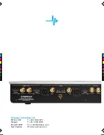
7 Phono Inputs
The Audiant VP3 Vinyl preamplifier has two separate input sections specifically designed to cater for
moving magnet (MM) and moving coil (MC) cartridges. Each set of phono inputs accept standard
unbalanced (RCA) analogue outputs from the corresponding cartridge type. The output of a mono
cartridge should be connected to the right channel of the corresponding input of the Audiant VP3 Vinyl
Preamplifier.
Note: High output MC cartridges can be connected to the MM input if the MC input results in
excessively high sound output.
8 Balanced Outputs
The balanced (XLR) outputs provide a balanced audio signal for connection directly to a preamplifier or
integrated amplifier.
The pin assignments of the balanced XLR output connectors are:
Pin 1: Shield
Pin 2: +ve signal (hot)
Pin 3: -ve signal (cold)
Please refer to the owner’s manual of your amplifier to verify that the pin assignments of the input
connectors correspond as above. If this is not the case, wire the cables so that the appropriate Audiant
VP3 Vinyl Preamplifier output pin connects to the equivalent preamplifier input pin.
Note: The balanced outputs employ entirely separate buffer stages to the unbalanced outputs, allowing
both outputs to be used simultaneously without degrading the performance of each other.
9 Unbalanced Outputs
The unbalanced (RCA) outputs provide a single-ended audio signal for connection directly to a
preamplifier or integrated amplifier.
Note: The unbalanced outputs employ entirely separate buffer stages to the balanced outputs, allowing
both outputs to be used simultaneously without degrading the performance of each other.
10 Gain/RIAA Adjustment Switches
The gain/RIAA adjustment switches provide further customisation to each input to allow greater
flexibility in matching the output of the Audiant VP3 Vinyl Preamplifier to your system. For more
information on these switches please refer to the Customisation section [page 11].
11 Phono Earth Terminal
The phono earth terminal connects to the earth lead from the tonearm cable of your turntable, if
required. If your turntable does not have a separate earth lead it may be advisable to run a wire from a
grounded screw on the turntable to this terminal. Turntables are very sensitive to hum and grounding
the table or cartridge to the Audiant VP3 Vinyl Preamplifier can help reduce hum.
Important:
Before making any connections, switch off the mains power to all components in your system.
1 Power On/Off
The Power switch turns power to the unit on and off.
2 Mains Power Socket
The Mains Power Socket is used with the removable mains power cord to supply your Audiant VP3 Vinyl
Preamplifier with power.
Before connecting your Audiant VP3 Vinyl Preamplifier to the mains power, please check the voltage
label on the rear panel to ensure that your preamplifier conforms to the power supply in your area.
Never attempt to connect the unit to an incorrect voltage – severe damage may result.
Note: The unit must always be earthed when connected to mains power. Use the earthed, moulded
mains lead supplied. Never use an unearthed mains plug, socket or adaptor with this unit. The mains
lead supplied may be fitted with a fused plug, depending on local regulations. If this is the case, always
replace this fuse with another of the same type and rating.
3 Mains Fuse
The mains fuse is user serviceable, and should always be replaced with the same type and rating (see
Technical Specifications section [page 16]).
Ensure your Audiant VP3 Vinyl Preamplifier is disconnected from the mains power before attempting to
change the fuse.
Note: Fuses do not usually blow without a reason. Any doubts about fuse failure should be conveyed
directly to your Perreaux dealer.
4 Trigger Input
The trigger input allows the Audiant VP3 Vinyl Preamplifier to be brought in and out of standby by a
remotely connected device; for example, another audio component or a home automation system. The
trigger input uses a mono 3.5mm (⅛”) plug and accepts voltages of 0V DC up to 12V DC. A trigger
voltage between 3V and 12V DC will bring the amplifier out of standby and it will enter standby when the
trigger voltage is 0V DC.
The trigger input plug must meet the specifications shown below:
Sleeve:
GND
Tip:
Signal
5 RS232 Port
The RS232 port allows external serial control of the Audiant VP3 Vinyl Preamplifier for custom install
use. A full command set is available on the Perreaux website. This port can also be used by authorised
Perreaux service personnel for software updates.