


28
Operation & Installation Manual
Signature Series Beer Dispensers (HP15, HP24 and HP48 models)
BEFORE YOU BEGIN...
Wash tapping devices thoroughly. Flush beer and faucet lines
and tapping device (keg coupler) with fresh water.
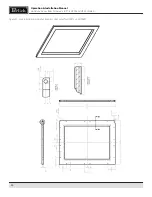
1. Locate the dispensing head, black beer line(s), and hose
clamp(s). Slide one end of each beer line onto the stainless
steel tubes which protrude out the bottom of the dispens-
ing head and clamp tight.
2. Insert the beer line(s) through the hole in the counter top.
Position the head in place and apply silicone around the
base of the dispensing head. Fasten using the 4 chrome
screws included with the dispensing head. Wipe off excess
silicone to complete the seal.
3. Using the 3/8” thick foam pad included in the tapping kit,
roll into a cylinder. From inside the cabinet, insert the foam
tube up through the hole in the ceiling of the cabinet,
through the hole in the counter top until it is firmly against
the insulation in the dispensing head. Cut away any excess
pad. Cut away any excess foam that extends into the cabi-
net that extends into refrigerator.
4. If installing a two or three faucet system, a CO2 manifold
will need to be installed. Locate the plastic manifold holding
bracket and a #10 x ½” sheet metal screw. On the left rear
side wall of the beer compartment there is a double row
of screws which run vertically. Remove one of the two top
screws and discard. Insert the sheet metal screw through
the bracket and into the hole vacated previously.
5. Locate the red CO2 lines, manifold and clamps. Slide one
end of each hose onto the barbed fittings on the manifold
and clamp. Insert the manifold into the bracket and secure
by squeezing the two sides together.
6. On a single beer system, locate the red CO2 hose. Slide one
end onto the barbed fitting of the regulator assembly and
clamp. On systems with two or three beers, locate the CO2
line that comes off the back side of the manifold assembly.
This is the hose not connected to a valve assembly. Slide the
hose end onto the barbed fitting of the regulator assembly
and clamp. For detailed information on connecting the
regulator to the CO2 cylinder, see page 31.
Содержание Signature Series HP15TS
Страница 2: ......
Страница 30: ...30 Operation Installation Manual Signature Series Beer Dispensers HP15 HP24 and HP48 models ...


