Perlick HA24BB1L Скачать руководство пользователя страница 4

© 2009

4

24” ADA-Compliant Series Operation / Installation Manual
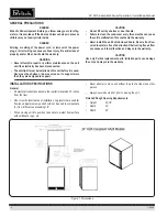
CAUTION

To prevent damage to the countertop and unit underneath, do not 
place heavy objects on countertop directly above the unit.

6.  Check interior door openings inside unit and ensure unit is level. 

SHELVING

IMPORTANT: To achieve maximum performance, interior louver open-
ings and fan guard openings should never be obstructed.

Refrigerator
The single door unit comes standard with two black vinyl coated 
adjustable full extension pullout shelves. 

Wine Reserve
The single door unit comes standard with five full extension black vinyl 
coated wine racks capable of storing 40 total wine bottles and addi-
tional storage on the bottom for 8 more bottles. Shelves are removable 
and adjustable to accommodate oversized (magnum) bottles. 
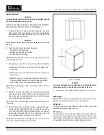
INSTALLATION

CAUTION

Finished flooring should be protected with appropriate material 
to avoid damage from moving the unit. 

If unit has been laid on its back or sides, place unit upright and 
allow minimum of 24 hours before connecting power. 

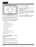
1.  Plug the unit into the 15 amp grounded outlet located in the instal-

lation opening. With power applied to the unit, check that lighting 
and cooling function operate properly, then turn off power to the 
wall outlet at the circuit breaker. 

WARNING

Shut off power to the wall outlet before installing unit into the 
opening.

2.  Check that the following are level and square:

- front face and interior opening
- installation opening and floor surface
- countertop bottom front edge

IMPORTANT: The floor under the unit must be at the same level as the 
surrounding finished floor.

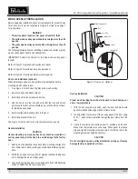
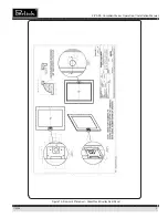
3.  If all surfaces are level, refer to Figure 3 and perform the following:

a. Measure from the floor to the bottom of the front edge of the 

countertop.

b. Measure the rear of unit cabinet from floor to top of cabinet, at 

back corners.

c.  Adjust rear legs so B measurement equals A measurement. 

Using an adjustable wrench or pliers, turn legs counterclock-
wise to raise the unit or clockwise to lower the unit.

IMPORTANT: Levelling legs should not extend more than 3/4” from 
bottom of unit.

4.  Slide the unit into position. Make sure the rear leveling legs slide 

under the anit-tip brackets. Push the unit into the opening until the 
door is flush with the surrounding cabinetry, or until the rear legs 
are tight against the anti-tip brackets.

IMPORTANT: The rear leveling legs must be engaged under the anti-
tip brackets.

5.  Shim the front of the unit so the front door is flush with the sur-

rounding cabinetry. Adjust the front legs to support the countertop 
at the shimmed height. Using an adjustable wrench or pliers, turn 
legs counterclockwise to raise the unit or clockwise to lower the 
unit. Countertop should be resting on top of the unit.

IMPORTANT: If countertop is not resting entirely on unit top, shim the 
countertop to prevent damage to the countertop.

Figure 3. Leveling 

Содержание HA24BB1L

Страница 1: ...llow instructions WARRANTY REGISTRATION To request information or service the model number and serial num ber must be provided This information is located on the inside ceiling of the unit and on the...

Страница 2: ...an the condenser every three months can cause the unit to malfunction This could void the warranty Never install the unit behind closed doors Be sure front lou vered toe plate is free of obstruction O...

Страница 3: ...3 prong receptacle in accordance with applicable electri cal codes DANGER Failure to comply with the above electrical guidelines may result in possible injury death fire or loss of property UNPACKING...

Страница 4: ...unit into the opening 2 Check that the following are level and square front face and interior opening installation opening and floor surface countertop bottom front edge IMPORTANT The floor under the...

Страница 5: ...ard to remove Figure 5 3 Place bracket at the desired position Push the rear hook into the rear key slot Set front of bracket on the wall hook 4 Repeat for other bracket s 5 Push extenders completely...

Страница 6: ...ositions are correct unlock should be up lock should be horizon tal Adjust as necessary 5 Install overlay with lock assembly to the door 6 Install lock bracket to the unit See Figure 7A 8A and 9A for...

Страница 7: ...HINGE KITS Part number 67439R to switch to Right Hinging Part number 67439L to switch to Left Hinging Step 1 Support door in the open position as shown Remove Hinge Pin Step 2 Pull door to the side t...

Страница 8: ...2008 8 24 C Series Operation Installation Manual 2009 8 24 ADA Compliant Series Operation Installation Manual Figure 7 Glass Wood Overlay Door Panel...

Страница 9: ...2008 9 24 ADA Compliant Series Operation Installation Manual Figure 7A Door Lock Placement Glass Wood Overlay Door Panel...

Страница 10: ...2008 10 24 ADA Compliant Series Operation Installation Manual Figure 8 Solid Wood Overlay Door Panel...

Страница 11: ...2008 11 24 ADA Compliant Series Operation Installation Manual Figure 8A Door Lock Placement Solid Wood Overlay Door Panel...

Страница 12: ...2008 12 24 ADA Compliant Series Operation Installation Manual Figure 9 Solid Wood Overlay Drawers...

Страница 13: ...2008 13 24 ADA Compliant Series Operation Installation Manual Figure 9A Door Lock Placement Solid Wood Overlay Drawers...

Страница 14: ...temperature especially at the top and cause the refrigera tion system to run longer Loading Product IMPORTANT Before storing perishables allow unit to run for a mini mum of 24 hours to allow temperat...

Страница 15: ...other routing maintenance Cleaning To clean stainless steel exterior or interior surfaces use a soft non abrasive stainless steel cleaner to wipe down the surfaces Glass doors can be cleaned using any...

Страница 16: ...ilding circuit breaker or fuse on Is the control set properly Is the condenser area clean The refrigerated compartment is warmer than usual Is the control set properly Is the light staying on Is the c...

Страница 17: ...Department 8300 W Good Hope Road Milwaukee WI 53223 E mail us at warrantyserv perlick com To obtain product service replacement parts or accessories Use only genuine Perlick replacement parts and acc...

Страница 18: ...bused operating with low voltage wiring not conforming electrical codes improperly maintained or modified The original Bill of Sale delivery date or serial number cannot be verified Defective parts ar...

Страница 19: ...2008 19 24 ADA Compliant Series Operation Installation Manual...

Страница 20: ...3223 1 800 558 5592 Fax 414 353 7069 www perlick com Perlick is committed to continuous improvement Therefore we reserve the right to change specifications without warning 2011 24 ADA Compliant Series...

Отзывы: