Perle IDS-509GPP Скачать руководство пользователя страница 2

IDS-509GPP Switches Quick Start Guide


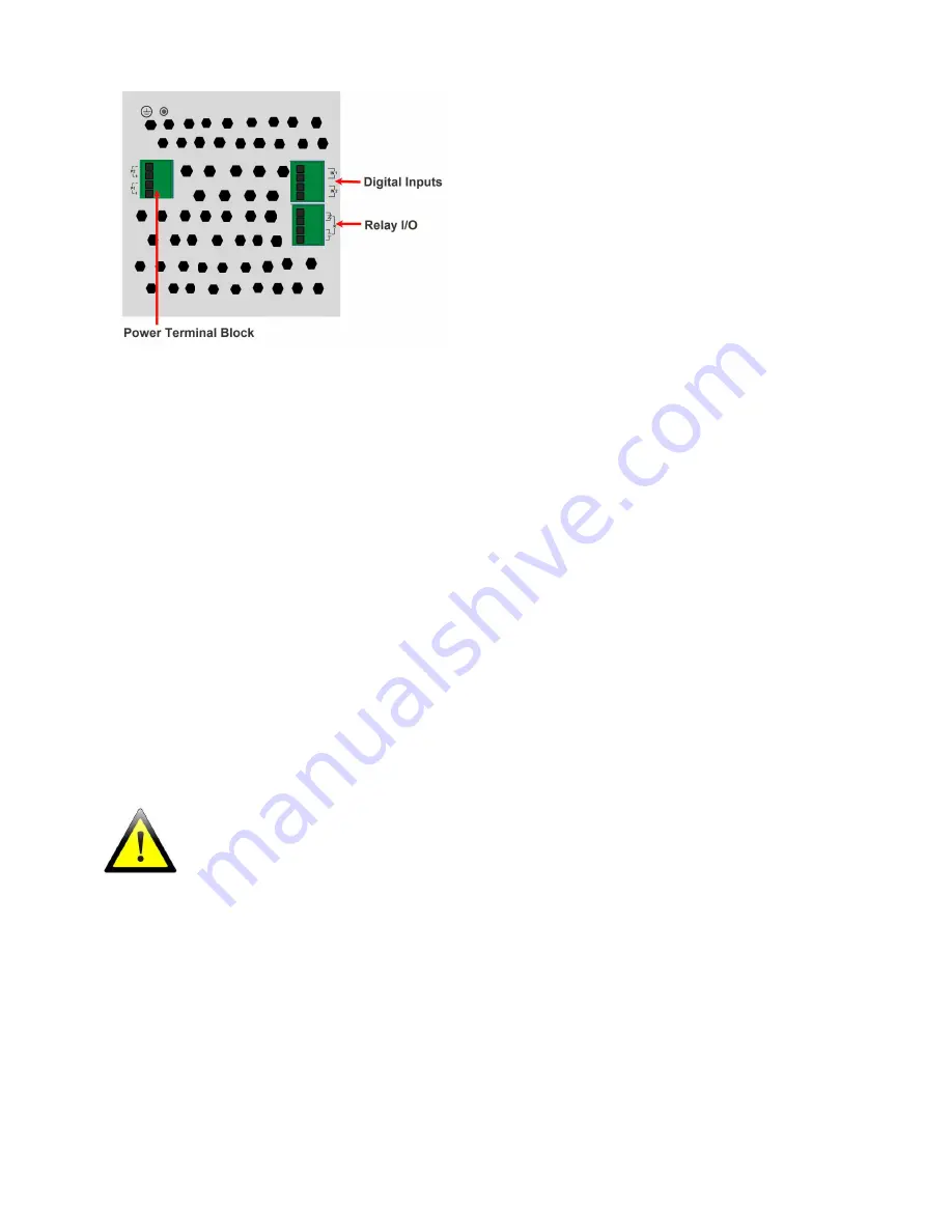
Wiring the Terminal Block 


Connecting the switch to ground (optional) 

If your installation requires additional grounding, refer to the Hardware Installation 
Guide for information on connecting ground. 

Connecting power to the IDS switch 

You may connect both sets of power inputs to provide redundant power.  

1.


Ensure the power source is off prior to connection. 

2.


Using a pair of 12-16AWG wires, strip them both 7-8mm (5/16”). 

3.


Loosen the terminal block screws and connect positive (+) / negative (-) wires in 
the +/- terminals. 

4.


Tighten terminal screws (0.51Nm torque). Ensure the wires are securely fastened. 

5.


Re-insert the terminal block connector if removed. Turn power on at source. Check 
LED indicators for status. 

6.


Connect P2 (power source 2, beginning at Step 1. 


For complete wiring instructions and for all Hazardous Locations and general safety warnings 
consult the Hardware Installation Guide. 


Connecting PoE/PoE+ devices 


Supports IEEE 802.3af (Type 1) and IEEE 802at-2009(Type 2) standards 


For PoE devices up to 15.4 watts per port 


For PoE+ devices up to 30 watts per port 

Connecting Ethernet 

Connect network or devices to Ethernet ports (1-9) using Cat5/5e Ethernet cables 

Содержание IDS-509GPP

Страница 1: ...com downloads IDS 509GPP Hardware Installation Guide IDS Managed Switches User Guide Pro Feature Set IDS Managed Switches CLI Guide Pro Feature Set What s in the box The IDS switch Quick Start Guide this document Hardware Overview Front View Back View 1 Terminal Block for Power 1 2 7 PoE PoE Enabled Ethernet Ports 2 Status LEDs 8 SD Card Slot 3 Console Port serial 9 Digital Inputs Relay I O 4 Cons...

Страница 2: ...d connect positive negative wires in the terminals 4 Tighten terminal screws 0 51Nm torque Ensure the wires are securely fastened 5 Re insert the terminal block connector if removed Turn power on at source Check LED indicators for status 6 Connect P2 power source 2 beginning at Step 1 For complete wiring instructions and for all Hazardous Locations and general safety warnings consult the Hardware ...

Страница 3: ...1 or P2 providing power within specifications SYS System status Green blinking System booting Green solid System operating normally Green blinking fast Fast Setup mode activated Red Hardware fault or firmware load error Ethernet Port Link Speed Green and Yellow LEDs 1000 Mbps Green on Yellow off 100 Mbps Green on Yellow on 10 Mbps Green off Yellow on Note Flashing indicates activity Note Alr Alarm...

Страница 4: ...in the switch a small tool such as a paper clip will be required The yellow and green LEDs on an unused RJ 45 connector will flash rapidly to indicate where to plug in the Ethernet cable from your PC 3 Using a web browser enter to a well known webpage such as www google com you will be automatically directed to the IDS Get Started screen Note While in Fast setup mode the IDS switch will use an IP ...

Отзывы: