

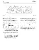


Illustration 23
g00285936
2.
While the dial indicator is in the position at location
(C) adjust the dial indicator to 0.0 mm (0.00 inch).
Push the crankshaft upward against the top of the
bearing. Refer to the illustration 23 . Write the
measurement for bearing clearance on line 1 in
column (C).
Note:
Write the measurements for the dial indicator
with the correct notations. This notation is necessary
for making the calculations in the chart correctly.
3.
Divide the measurement from Step 2 by two. Write
this number on line 1 in columns (B) and (D).
4.
Turn the flywheel in order to put the dial indicator
at position (A). Adjust the dial indicator to 0.0 mm
(0.00 inch).
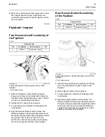
Illustration 24
g00285932
Checking bore runout of the flywheel housing
5.
Turn the flywheel counterclockwise in order to put
the dial indicator at position (B). Write the
measurements in the chart.
6.
Turn the flywheel counterclockwise in order to put
the dial indicator at position (C). Write the
measurement in the chart.
7.
Turn the flywheel counterclockwise in order to put
the dial indicator at position (D). Write the
measurement in the chart.
8.
Add the lines together in each column.
9.
Subtract the smaller number from the larger
number in column B and column D. Place this
number on line III. The result is the horizontal
eccentricity (out of round). Line III in column C is
the vertical eccentricity.
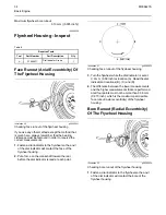
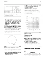
Illustration 25
g00286046
Graph for total eccentricity
(1) Total vertical eccentricity
(2) Total horizontal eccentricity
(3) Acceptable value
(4) Unacceptable value
10.
On the graph for total eccentricity, find the point of
intersection of the lines for vertical eccentricity and
horizontal eccentricity.
11.
The bore is in alignment, if the point of
intersection is in the range that is marked
“Acceptable”. If the point of intersection is in the
range that is marked “Not acceptable”, the
flywheel housing must be changed.
i02995981
Crankshaft
Thrust
-
Measure
Table
9
Required Tools
Tool
Part Number
Part Description
QTY
A
21825617
Dial Indicator Group
1
M0064276
35
Содержание 4008-30 SD8
Страница 14: ...Starting System Components 14 M0064276 Electrical System ...
Страница 41: ......
Страница 42: ...M0064276 2015 Perkins Engines Company Limited All Rights Reserved 42 December 2015 ...


