


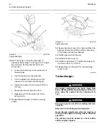


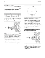

Illustration 9
g01241598
Typical example
10.
Use Tooling (B) to check the valve lash. If
necessary, follow steps 10.a through 10.f to adjust
the valve lash. Set the valve lash to 0.4 mm
(0.016 inch).
a.
Loosen the locknut (9) on the rocker arm of
the inlet valve.
b.
Use Tooling (B) to set the valve lash.
c.
Turn the adjuster (8) until the pad on the
rocker arm is in contact with Tooling (B).
d.
Tighten the locknut (7) to a torque of 50 N·m
(37 lb ft).
e.
Ensure that the valve lash is correct.
f.
Repeat step 10 for the rocker arm of the
exhaust valve.
11.
Repeat steps 5 through 10 for the remaining
rockers.
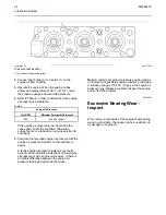
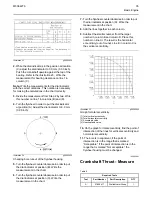
Illustration 10
g01241917
Typical example
12.
Ensure the rocker cover (2) is clean and free from
damage. Ensure the joint face of the rocker base
(10) is clean and free from damage.
13.
Install a new joint (not shown).
14.
Install the rocker cover (2).
15.
Install the capscrews (1). Tighten the capscrews
to a torque of 4 N·m (35 lb in).
16.
Repeat steps 12 through 15 for the remaining
rocker covers.
i02863396
Turbocharger
Hot engine components can cause injury from
burns. Before performing maintenance on the en-
gine, allow the engine and the components to
cool.
Personal injury can result from rotating and mov-
ing parts.
Stay clear of all rotating and moving parts.
Never attempt adjustments while the machine is
moving or the engine is running unless otherwise
specified.
The machine must be parked on a level surface
and the engine stopped.
20
M0064276
Содержание 4008-30 SD8
Страница 14: ...Starting System Components 14 M0064276 Electrical System ...
Страница 41: ......
Страница 42: ...M0064276 2015 Perkins Engines Company Limited All Rights Reserved 42 December 2015 ...


