Assembly and Operation Manual
10. Connect the half-frames in the zone of the upper power tube with bolts M6×20 – 5 pcs.
(wrench SW5) to obtain a sturdy construction. Use plugs for the bolt holes.
11. Check all threaded connections of the canopy frame and tighten them.
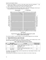
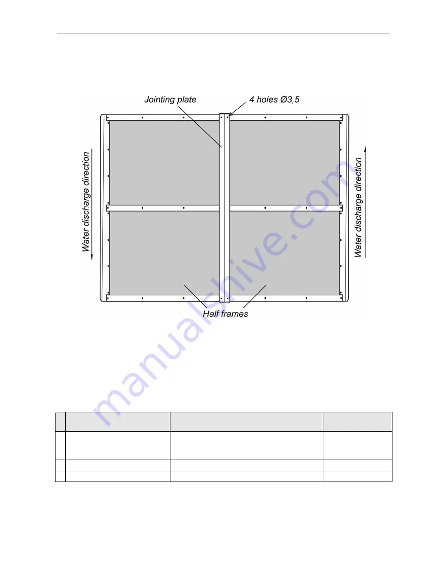
12. Set the jointing plate into working position, fixing it with 4,2×16 self-tapping screws (4 pcs.),
having preliminary drilled the holes by drill Ø3,5 (see Figure 6).
Figure 6 The top view of the connected half-frames #1 and #2
with the installed jointing plate
The canopy is installed. Consult with PERCo Technical Support Department when necessary.
8 TRANSPORTATION AND STORAGE
The canopy in the standard delivery set (Section 4) is packed in three transport boxes, which
protect its components from damage during transportation and storage.
Table 1 Overall dimensions and boxes contents
№
Dimensions
(Length × width × height)
Contents
Weight (gross),
not more than
1 191×126×57
Canopy’s half-frame #1 assembled - 1 pcs.
Jointing plate - 1 pcs.
Fasteners – 1 kit
45
2
191×126×57
Canopy’s half-frame #2 assembled - 1 pcs.
44
3
223×53×31
Posts – 4 pcs.
21
The canopy in the original package should be transported only in closed freight containers or other
closed type cargo transport.
During storage and transportation the boxes can be stacked no more than 2 layers high.
10
Содержание RTC-15.3
Страница 1: ...ASSEMBLY AND OPERATION MANUAL WARRANTY CARD RTC 15 3 Protective Capony...
Страница 2: ...Protective Canopy RTC 15 3 Assembly and Operation Manual Warranty Card...
Страница 15: ......
Страница 16: ......
Страница 18: ...www perco com...


