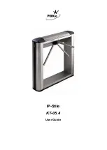
IP-Stile KT-05.4
5
2.1 Indication module
To inform on a current status of the turnstile both front sides of the turnstile housing
feature indication modules (ref. Figure 1, parts 8), with card readers built-in under, on the
internal side of the cover. The indication module has 3 mnemonic indicators (ref. Figure 2):
–
Green indicator of authorized passage.
IP-Stile is unlocked in this direction.
–
Yellow indicator: card presentation or operator command are expected.
IP-Stile is locked in this direction.
–
Red indicator of passage ban.
IP-Stile is locked in this direction.
Figure 2. Visual indicators of the indication module
2.2 RC-panel
The RC-panel is designed as a small desktop device with a shock-proof ABS plastic case
and is intended for setting and indicating operating modes when the turnstile is operated
manually. The RC-panel overall view is shown in Figure 3.
Figure 3. RC panel overall view
1, 2, 3 – buttons
LEFT
,
RIGHT
,
STOP
for setting the passage mode;
4, 5 – green indicators
«Left»
,
«Right»
; 6 – red indicator
«Stop»,
7 – RC cable.
There are three control buttons on the RC front panel intended for setting the turnstile
operating modes. The LED indicators are located above the buttons. The middle button on
the RC-panel (hereinafter — the
STOP
button) is intended to set the turnstile to the
“Always locked” mode. The left (
LEFT
) and the right (
RIGHT
) buttons are intended to
unlock the turnstile for passage in the chosen direction.
Содержание IP-Stile KT-05.4
Страница 1: ...IP Stile KT 05 4 ASSEMBLY AND OPERATION MANUAL...
Страница 2: ...IP Stile KT 05 4 User Guide...
Страница 14: ...www perco com...


