


iQntrol DOS-MODBUS
Original manual in German Version 1.0.2 2022.10.06
7/39
4
Scope of delivery – device description
4.1
Scope of delivery
The IQntrol DOS MODBUS is delivered with the following standard accessories.
- Buffer solutions pH7, pH4, redox test solution
- Electrode cleaner, distilled water
- Glass beads, electrolyte solution, replacement gaskets
- 2 pc. ½“ measuring water ball valve with immersion pipe
- 7 m each measuring water pipe 6x1 mm in PE and PTFE, respectively
Customer-specific or order-related modifications are possible.
4.2
Check for transport damage
Please check the device and all accessories immediately upon receipt for transport damage and completeness.
4.3
Identification of the device
For spare part orders and troubleshooting, it is useful to know the device serial number and software version. The device serial
number is located on the identification plate on the right side of the control housing. The programme version can be called up via
the menu item Service
Info.
4.4
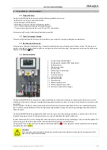
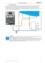
Device description
1
2
2
5
7
4
6
8
9
13
3
10
11
12
1.
Control IQntrol DOS MODBUS
2.
Dosing pumps Standard SR10 (optional Sa)
3.
Buffer solutions
4.
Redox test cylinder
5.
pH electrode
6.
Measuring cell illumination
7.
Dosing valves
8.
Flow control valve
9.
Flow monitoring
10.
Redox electrode
11.
Test water tap
12.
Measuring water inlet
13.
Measuring water return flow
14.
Suction set (not visible in image)
The IQntrol DOS MODBUS is delivered as a ready-assembled unit. All parts are mounted on a plastic plate. This ensures a quick
installation of the device. It also goes toward preventing potential execution errors on the part of the installation personnel, as far
as possible.
For the transport, the factory merely removes the pH electrode from the measuring cell and delivers it in a separate protective
box. In order to avoid deformation of the dosing hoses during extended storage, the two dosing cartridges have been pulled off
the motor shaft.
The IQntrol DOS MODBUS is equipped with a touch-sensitive touch screen. By touching a symbol or a numeric value, this will be
activated for parametrisation. The adjustment menus come with additional text-based instructions.
In order to eliminate the risk of confusing both chemicals as far as possible, the dosing technology is colour-coded throughout. The
colour-coding runs from the suction set over the associated dosing pump to the dosing valve.
The parts used for pH value control are located to the left and coded in red. The components used for disinfection are located on
the right and coded in yellow.
CAUTION!
If the two chemicals are switched, this leads to a malfunction of the addition of chemicals to the pool water! This
may result in significant overdosing!