background image

10

Door Interrupt System with FYQLA1-140R-3 Logic Amplifier

System inputs

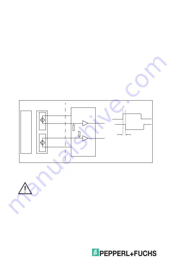
The six device inputs allow the user to monitor up to six functional switch devices. 

Each device must have two channels of output, one sourcing output and one 

sinking output. These outputs must operate in tandem for a valid switch function 

to be recognized by the FYQLA1-140R-3. If the output channels of the switches are 

not functioning in a synchronized manner the amplifier will not accept the switch 

closure as a valid. The allowable timing between closure of switch channel A and 

channel B is approximately one second. If any given pair of switch channels does 

not transition to the proper state in the minimum time, then the monitor will issue a 

fault on that switch channel and prevent the output from closing.

Reset faulted state

If an invalid door switch sequence is detected by the Channel A and Channel B 

synchronization, the output safety relays will open and red fault LED will blink. 

Reset is accomplished by a power down/power up sequence.

Output relays to de-energize equipment

When an invalid input condition is recognized by the door interrupt 

system, the output safety relay will be de-energized. This will cause the 

relay contact pair to open. Be sure to verify the contact power ratings 

when applying these relay outputs to energize/de-energize associated 

equipment. 

Hardware


Inputs

• 

Six switch inputs compatible with dual channel devices

         ▸  Fuchs’ 50FY41 series magnetic sensors

Attention

Actuator                  Switch     

Channel A

Channel B

Monitor input

Channel A

Channel B

Minimum time 

between transitions

Содержание FYQLA1-140R-3

Страница 1: ...FACTORY AUTOMATION INSTRUCTION MANUAL Door Interrupt System With FYQLA1 140R 3 Logic Amplifier Original Instructions ...

Страница 2: ...ndicators 11 Indicator status table 11 Guided relays 12 Input devices 12 Magnetic switches 12 Nominal offset distances 13 Device dimensions 13 Installation 14 Installation requirements 14 Clearance around the device 14 General safety notes 14 Installation and testing 14 Electrical installation 15 Powering the device 15 Wiring requirements 15 Wiring diagram 16 Electrical connection 17 Commissioning...

Страница 3: ... for future reference Directly after opening the packaging please ensure that the device is intact and that the package is complete Copyright Copyright 2017 by Pepperl Fuchs Inc All rights reserved The company Pepperl Fuchs Inc claims copyright on this documentation To modify extend hand over to a third party or copy this documentation without written approval by the company Pepperl Fuchs Inc is e...

Страница 4: ...halstraße 200 68307 Mannheim Germany www pepperl fuchs com Declaration of conformity www pepperl fuchs com Directives observed 2006 42 EC Machinery Directive 2014 30 EU EMC Directive 2014 35 EU Low Voltage Directive Standards observed EN ISO 13849 1 2015 EN 60664 1 2008 EN 61326 1 2012 EN 61326 3 2 2008 Documentation officer Pepperl Fuchs GmbH Lilienthalstraße 200 D 68307 Mannheim Germany Document...

Страница 5: ...s Functional Safety Management FSM considering a full lifecycle approach must be used to guarantee functional safety Competence is essential in the delivery of functional safety The application must be planned by qualified personnel that know how to apply the necessary standards and regulations The door interrupt system must be installed by qualified personnel who are properly trained in the insta...

Страница 6: ...ntrol component in the safety system The person performing the test should be familiar with the different guards and controls on the equipment This test should be performed daily If the machine is not in continuous operation test before each use See the Daily inspection flow diagram pages 8 9 Regular maintenance testing It is recommended to test the door interrupt system regularly to verify proper...

Страница 7: ...relay status indicators LED relay power indicator Together with the 50FY41 series sensors and 52FY31 series actuators the FYQLA1 140R 3 can be used to protect one or more points of hazardous areas Functions Power up sequence After power is applied to the system an internal system check is performed verifying the functional logic and connected switch conditions If any errors are detected at power u...

Страница 8: ...Input 1a LED Input 1b LED Input 2a LED Input 2b LED Input 3a LED Input 3b LED Input 4a LED Input 4b LED Input 5a LED Input 5b LED Input 6a LED Input 6b LED Fault LEDs All guards closed Off at all times other than momentarily at power up Only input 1 open Only input 2 open Only input 3 open Only input 4 open Only input 5 open Only input 6 open Daily inspection p p Input status LEDs p Green LED Red ...

Страница 9: ...lit Wait 3 5 seconds Is the red fault LED lit or blinking Close open guard door Have all inputs been tested Document results in inspection records No No Yes Yes Yes Yes Yes Yes No No Open or remove first guard door equipped with the 50FY41 switch Done Passed Shut down machine contact repair technician No Open or remove next guard door equipped with the 50FY41 switch ...

Страница 10: ...e then the monitor will issue a fault on that switch channel and prevent the output from closing Reset faulted state If an invalid door switch sequence is detected by the Channel A and Channel B synchronization the output safety relays will open and red fault LED will blink Reset is accomplished by a power down power up sequence Output relays to de energize equipment When an invalid input conditio...

Страница 11: ...g conditions Input switch sequence error channel A and channel B timing Output relay contact monitor fault Indicator status table Condition Switch Status Relay 1 Status Relay 2 Status Red Fault LEDs SR1 Contact Status Red Channel 1 LED Red Channel 2 LED Red Open LED Green Closed LED Red Open LED Green Closed LED Normal Operation Door Sensor Open Door Sensor Closed p p Faults Door Sensor Fault1 Rel...

Страница 12: ...egrated circuits that are connected independently When exposed to this magnetic actuator and properly aligned the sensor responds with an output Approved devices 50FY41 series Hall effect door interrupt sensor 52FY31 series Keyed hall effect magnetic actuator NOTE These are the only approved devices that should be used 50FY41 sensor alignment Ensure the alignment of the sensor and magnetic actuato...

Страница 13: ...istance mm in Offset Max Actuator Distance Off Distance 0 zero 2 5 0 1 10 0 4 3 8 0 15 1 3 0 05 10 0 4 7 5 0 3 0 zero 10 0 4 25 4 12 7 2 x ø5 39 25 4 39 Cable Length 50FY41 hall effect sensor 52FY31 magnet actuator 25 4 12 7 2 x ø5 39 25 4 39 Device dimensions for reference only dimensions in mm Nominal offset distances ...

Страница 14: ... the device to allow for proper cooling and ventilation of the control unit General safety notes Installation and testing After installation the FYQLA1 140R 3 and all connected devices must be tested to ensure proper wiring and operation All wiring should be verified before applying power to the unit Once power is applied each door switch should be opened to verify proper operation of the system P...

Страница 15: ...respond to the required category according to ISO 13849 1 2015 Wiring requirements GREEN terminal block Input supply power Relay contact output BLACK terminals CH1 CH 6 50FY41 switch inputs Improper installation This product is designed to conform to the technical requirements of ISO 13849 1 2015 To ensure compliance with these requirements 50FY41 series sensors and 52FY31 series actuators MUST be...

Страница 16: ...16 Door Interrupt System with FYQLA1 140R 3 Logic Amplifier Wiring diagram FYQLA1 140R 3 ...

Страница 17: ...ncluded W normally open sourcing WHITE output B negative BLACK ground O normally open sinking ORANGE output If less than six sensors are connected to the safety monitor install two 22 K resistors one between R W and one between B O into the unused inputs Do not connect or remove wires with power applied Warning x1 x2 x3 x4 50FY41 Red Orange White Black R W B O R W B O ...

Страница 18: ...lar Observe the relevant laws and local regulations Validation of the application You may commission the system only if all pretests were successful Validation may be performed only by qualified personnel The general acceptance comprises the following tests Check whether the components used correspond to the required Performance Level in accordance with EN ISO 13849 1 2015 Check that the devices c...

Страница 19: ...Fault conditions can be cleared only upon power down power up of the door interrupt system Technical support Troubleshooting Problem Probable cause Remedy No LEDs illuminated No supply power Verify incoming power is present Blown internal fuse Verify input power is within spec and then replace fuse Fault LED is flashing and single LED is lit for a sensor input while actuated or de actuated Misalig...

Страница 20: ...the sensor and or actuator in question Approvals UL508 Input specifications FYQLA1 140R 3 120 VAC 15 0 25A 45 to 65 Hz Input devices 6 dedicated noncontact hall effect door sensors 50FY41 series Switch voltage input 12 VDC 2 channel sink source Typical response time 20 ms switch open to contact open Power up time 3 s Output specifications Contact material AgCuNi 0 2 um Au Continuous current 5 mA t...

Страница 21: ...ns standard SN29500 Power supply failures are not included in the FMEDA a loss of power introduces the safe state It was assumed that the appearance of a safe error e g output in safe state would be repaired within 8 hours e g remove sensor burnout During the absence of the device for repairing measures have to be taken to ensure the safety function for example substitution by an equivalent device...

Страница 22: ...ew connection Terminal block sensor inputs Conductor cross section capacity 0 5 mm to 2 5 mm 22 to 14 AWG Cu Tightening torque 0 5 to 0 6 Nm 4 5 to 5 3 lb in Strip length 6 mm Connection method Terminal block screw connection General data Dimensions FYQLA1 140R 3 203 0 mm H x 135 0 mm W x 58 0 mm D Mechanical service life approx 1 000 000 operations Indicators Sensor status Relay status Fault stat...

Страница 23: ...GIC AMPLIFIER FYQLA1 140R 3 250 VAC 1 8 A SLOW BLOW IND CONT EQ 1EA5 R W B 0 3 R W B 0 4 R W B 0 5 R W B 0 6 R W B 0 C L O S E D O P E N RELAY CONDITION Twinsburg Ohio 44087 Phone 330 425 3555 630 A 250 VAC L1 120 1 8A 5A 250VAC L2 V R1 R1 LISTED 4X Ø 5 56 203 190 58 37 135 108 Dimensions for reference only dimensions in mm ...

Страница 24: ...ct to modifications Copyright Pepperl Fuchs Printed in USA TDOCT B1Z0_ENG 09 18 North Central American Headquarters Pepperl Fuchs Inc Twinsburg Ohio USA Tel 1 330 486 0002 E Mail fa info us pepperl fuchs com ...

Отзывы: