Pepperl+Fuchs BTC14N-GP-TS20-DP-N0 Скачать руководство пользователя страница 29

Box Thin Client for Industrial Applications

BIOS Settings

 2

01

9-

12

29

4.2

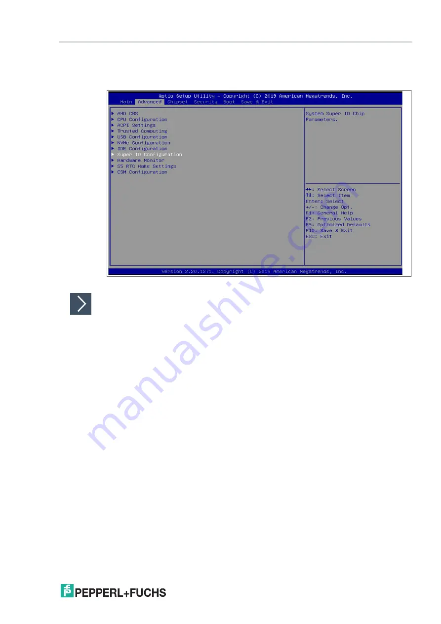
Changing Serial Interface Mode (RS-232, RS-485)

Select 

Advanced

 from the BIOS setup page.

Figure 4.3

"Advanced" BIOS menu

Configuring Advanced Settings

F81866 Super IO Configuration

 allows you to view and configure the Super I/O Chip 

parameters.

1.

Select the port you want to set using the arrow keys. Press ENTER.

2.

Select 

Enabled

 or 

Disabled

. Press ENTER in the pop-up window.

3.

The enabled port selects the appropriate setting change and device mode. Press ENTER.

Содержание BTC14N-GP-TS20-DP-N0

Страница 1: ...Box Thin Client for Industrial Applications BTC14N GP TS20 DP N0 Manual ...

Страница 2: ...sion as well as the supplementary clause Expanded reservation of proprietor ship Worldwide Pepperl Fuchs Group Lilienthalstr 200 68307 Mannheim Germany Phone 49 621 776 0 E mail info de pepperl fuchs com North American Headquarters Pepperl Fuchs Inc 1600 Enterprise Parkway Twinsburg Ohio 44087 USA Phone 1 330 425 3555 E mail sales us pepperl fuchs com Asia Headquarters Pepperl Fuchs Pte Ltd P F Bu...

Страница 3: ... 6 2 1 Application 6 2 2 RM Shell 5 8 2 3 Technical Data 8 2 4 Dimensions and Nameplates 10 3 Installation 11 3 1 Mounting 11 3 2 Electrical Connection 19 3 3 I O Connection 20 4 BIOS Settings 26 4 1 Creating a New BIOS Password 28 4 2 Changing Serial Interface Mode RS 232 RS 485 29 4 3 USB Configuration 31 4 4 Boot Configuration 32 4 5 Resetting the BIOS to Factory Settings 37 5 Service and Suppo...

Страница 4: ...claration of conformity Attestation of conformity Certificates Control drawings Instruction manual Other documents 1 1 2 Manufacturer 1 1 3 Target Group Personnel Responsibility for planning assembly commissioning operation maintenance and dismount ing lies with the plant operator Only appropriately trained and qualified personnel may carry out mounting installation com missioning operation mainte...

Страница 5: ...s are displayed in descending order as fol lows Informative Symbols Action This symbol indicates a paragraph with instructions You are prompted to perform an action or a sequence of actions Danger This symbol indicates an imminent danger Non observance will result in personal injury or death Warning This symbol indicates a possible fault or danger Non observance may cause personal injury or seriou...

Страница 6: ...dard version of the BTC14 is BTC14N GP TS20 DP N0 which is equipped with 4 GB RAM Up to four Full HD capable monitors can be connected to the native Display Ports TM Warning User access Do not open the device The BTC14 is a closed unit with no user accessible parts Note Radio interference This device has been tested and found to comply with the limits for a Class A digital device pursuant to part ...

Страница 7: ...o four 4 K monitors at 60Hz Figure 2 3 Example of a scenario with different Monitors 4 K Ultra HD at 60 Hz and Full HD monitors 8 GB RAM If a 4 K monitor needs to be connected to the BTC14 the 8 GB RAM option needs to be cho sen Full DH and 4 K monitors can than be combined as necessary Quad Monitor Setup with 4K Quad Monitor Setup with Full HD 4K 4K 60 Hz 4K 60 Hz 4K 60 Hz 4K 60 Hz 4K 60 Hz Full ...

Страница 8: ...ctive conformity Software Ambient conditions Note Please visit www pepperl fuchs com regularly to check for the latest version of RM Shell Processor AMD Ryzen Embedded V1202B RAM 4 GB DDR4 Mass storage 32 GB M 2 MSATA MLC Power supply Input voltage 12 28 V DC Input current max 4 46 A 1 48 A Input via 2 5 mm power socket with double insulation from the power supply Interface type front 2 x USB 2 0 ...

Страница 9: ... resistance 3 grms 5 500 Hz Housing material aluminum body and sheet metal painted powder coated Degree of protection IP4x Mass 1 6 kg Dimensions 260 mm x 200 mm x 56 mm Mounting Desktop or wall mounting VESA mount and DIN rail mounting via optional adapter Note passive cooling no moving parts Power supply not included UL approval UL Listed for Canada and USA E223772 NRAQ NRAQ7 in preparation Appr...

Страница 10: ...ed Windows operating systems and is affixed to the back of the device Nameplate Hot surface Certificate of Authenticity COA 150 200 246 259 232 56 BTC14N GP TS20 DP N0 Part No 70110484 100001 Manuf Serial No This device complies with part 15 of the FCC Rules Operation is subject to the following two conditions 1 This device may not cause harmful interference and 2 this device must accept any inter...

Страница 11: ...evice is installed in a housing power dissipation from the device must be taken into account see chapter 3 2 Vertical installation provides optimal cooling since air passes through the cooling fins Observe the following recommended distances to other electrical components or to a housing wall Below the device if mounted vertically 100 mm All other sides 50 mm Figure 3 1 Horizontal mounting desktop...

Страница 12: ...tions Installation Figure 3 2 Vertical mounting 50 mm 50 mm 50 mm 100 mm 50 mm Caution Ambient conditions Do not operate the device outside the specified ambient temperature Warning Hot surface The surface of the device may become hot during operation ...

Страница 13: ... rail adapter to the back of the BTC14 Use the thread on the bottom of the BTC14 to secure the adapter Tighten the supplied screws to a tightening torque of 0 4 Nm Figure 3 3 2 There is a movable clamp on the top of the DIN rail adapter Install the BTC14 at a slight angle with the movable clamp over the DIN mounting rail Apply light pressure to pull the BTC14 downward and clamp the adapter into th...

Страница 14: ...2019 12 14 Box Thin Client for Industrial Applications Installation Figure 3 4 1 2 ...

Страница 15: ...y and the following installation diagram to secure the device to the wall Use wall anchors if nec essary Caution Insufficient load capacity If the mounting surface for wall and vertical mounting does not have sufficient load capacity the device may fall and be damaged It is the responsibility of the installer to select a suitable location with sufficient strength for the equipment ...

Страница 16: ...gram VESA Mounting 1 Attach the VESA fixture to the VESA arm or the back panel of the monitor using the screws provided by the monitor manufacturer 1 2 4 5 Ø 8 12 24 9 150 99 9 199 8 6 65 245 8 Note The VESA fixture is not included on BTC14 delivery You can order a VESA fixture as accessories see chapter 6 ...

Страница 17: ...Box Thin Client for Industrial Applications Installation 2019 12 17 Figure 3 8 Figure 3 9 2 Secure the BTC14 to the VESA fixture using the supplied screws 3 Screw M4 tightening torque 0 7 0 1 Nm ...

Страница 18: ...2019 12 18 Box Thin Client for Industrial Applications Installation Figure 3 10 Figure 3 11 ...

Страница 19: ...nt dust ingress leave the dummy plugs in ports that are not in use 2 Connect the BTC14 to the network via the Ethernet port 3 Connect the BTC14 to the mouse and keyboard via the USB 2 0 port 4 Connect the BTC14 via one or serveral DisplayPorts to the corresponding display The DisplayPort interface provides mechanical strain relief to protect against vibration Locking mechanisms are available as ac...

Страница 20: ...Port Overview No Interface type Description Front Antenna opening x 2 dummy plug Dummy plug antenna connections one on the left and one on the right USB1 USB 2 0 x 2 Audio Line output x 1 Symbol On off switch Back Ground connection Not required for standard installations 2 3 4 1 POWER INPUT DC 12 28V 2 1 1 2 3 4 5 7 9 11 6 8 10 12 13 14 1 2 3 4 5 ...

Страница 21: ...rimary port DisplayPort 2 DP 1 2 up to 2 x 4K Ultra HD at 60 Hz Up to 3 Full HD monitors via series connection DisplayPort 1 1 Only four of these USB ports can be operated simultaneously in high current mode max 14 W Pin Type Description 1 DCD Data Carrier Detect E 2 RxD Received Data E 3 TxD Transmitted Data A 4 DTR Data Terminal Ready A 5 M Ground 6 DSR Data Set Ready E 7 RTS Request to Send A 8...

Страница 22: ...ceive data I O for half duplex mode 2 Data Transmit receive data I O for half duplex mode 3 Not con nected 4 Not con nected 5 M Signal ground 6 Not con nected 7 Not con nected 8 Not con nected 9 Not con nected Pin Type 1 Transceive Data 2 Transceive Data 3 Receive Data 4 Bidirectional Data 5 Bidirectional Data 6 Receive Data 7 Bidirectional Data 8 Bidirectional Data 1 9 5 6 1 8 1 2 ...

Страница 23: ...e0 DP Data 0 Output 2 GND Ground 3 ML_Lane0 DP Data 0 Output 4 ML_Lane1 DP Data 1 Output 5 GND Ground 6 ML_Lane1 DP Data 1 Output 7 ML_Lane2 DP Data 2 Output 8 GND Ground 9 ML_Lane2 DP Data 2 Output 10 ML_Lane3 DP Data 3 Output 11 GND Ground 12 ML_Lane3 DP Data 3 Output 13 CONFIG1 CAD Cable adapter detection Input 14 CONFIG2 Ground pull down 15 AUX_CH Auxiliary channel Input output 16 GND Ground 1...

Страница 24: ... 2 USB_D0M I O Data 3 USB_D0P I O Data 4 USB_GND GND Pin Type Description Input out put 1 VBUS 5 V fused Output 2 D Data channel USB 2 0 Input output 3 D Data channel USB 2 0 Input output 4 GND Ground 5 RX Data channel USB 3 0 Input 6 RX Data channel USB 3 0 Input 7 GND Ground 8 TX Data channel USB 3 0 Output 9 TX Data channel USB 3 0 Output 1 2 3 4 1 2 3 4 9 8 7 6 5 ...

Страница 25: ...nput output 4 BI_DC Bidirectional data C input output 5 BI_DC Bidirectional data C input output 6 BI_DB Bidirectional data B input output 7 BI_DD Bidirectional data D input output 8 BI_DD Bidirectional data D input output No Type Description Orange LED On port is active no data exchange Flashing port is active data exchange Off port is active Green LED Off 10 Mbit s connection Flashing 100 Mbit s ...

Страница 26: ... the device Shortcut Function Description Left right arrow keys Select screen Menu bar and select a BIOS setup page e g the main page Up down arrow key and click Select ele ment Select a BIOS setup element or a subpage Enter dou ble click Select Select an option to edit its value or access a submenu Change option Change the field value of a specific setup element e g date time F1 General Help Disp...

Страница 27: ...2 Navigate to month day and year in sequence Enter the appropriate value Press ENTER to move to the next field 3 Press F10 to save the changes Setting the System Time 1 Use the arrow buttons to set the time 2 Navigate to hour minute and seconds in sequence Enter the appropriate value Press ENTER to move to the next field 3 Press F10 to save the changes BIOS Setup Menu ...

Страница 28: ...S 1 Select Setup Administrator Password using the arrow keys and press Enter 2 Enter a password of at least 3 characters The password can be up to 20 characters long and is case sensitive 3 Re enter the password when the pop up window appears prompting you to confirm the password Note After changing note down the password and keep it in a safe place Pepperl Fuchs assumes no liability in the event ...

Страница 29: ...ure 4 3 Advanced BIOS menu Configuring Advanced Settings F81866 Super IO Configuration allows you to view and configure the Super I O Chip parameters 1 Select the port you want to set using the arrow keys Press ENTER 2 Select Enabled or Disabled Press ENTER in the pop up window 3 The enabled port selects the appropriate setting change and device mode Press ENTER ...

Страница 30: ...ure 4 5 Mode Select Settings for Serial Port 1 Device settings Mode select IO 3F8h IRQ 4 IO 3F8h IRQ 3 4 5 6 7 9 10 11 12 IO 2F8h IRQ 3 4 5 6 7 9 10 11 12 IO 3E8h IRQ 3 4 5 6 7 9 10 11 12 IO 2E8h IRQ 3 4 5 6 7 9 10 11 12 RS 232 RS 422 RS 485 RS 422 Termination Resistor RS 485 Termination Resistor ...

Страница 31: ... USB parameters The USB device displays the USB device detected by the BIOS during the power on self test Figure 4 6 Enabling and disabling the USB device Enabling and Disabling the USB Device 1 Select USB Mass Storage Driver Support using the arrow keys and press Enter 2 Select Enabled or Disabled as needed Press Enter in the pop up window ...

Страница 32: ...Figure 4 7 Boot BIOS menu You can change the following settings on the Boot configuration page Setup Prompt Timeout Sets the time period within which the Delete key must be pressed to enter the BIOS at power on BootUp NumLock State Enables and disables the numeric keys on the keyboard Set the PXE ROM before changing boot options ...

Страница 33: ...ct Advanced from the BIOS setup page Figure 4 8 Configuring the compatibility support module 2 Select CSM Configuration with the arrow keys and press ENTER 3 Select Network with the arrow keys Press ENTER Select UEFI or Legacy depending on what your PXE server supports Press ENTER in the pop up window ...

Страница 34: ...to set the priority of all boot devices 1 Using the arrow keys select the Boot Option Priority you wish to change Press ENTER The options window will open Figure 4 9 Boot option priorities 2 Select the equipment category PXE IBA GE Slot 0100 v1548 or Windows Boot ManagerP1 M 2 S42 3ME4 depending on the port being used Press ENTER ...

Страница 35: ...gure 4 10 Power Management 1 Select Advanced from the BIOS setup page 2 Select FCH Common Options with the arrow keys and press ENTER 3 Select AC Power Loss Options and press ENTER Specify what state to go when power is re applied after a power failure choose between Power off and Power on ...

Страница 36: ...em configuration save the changes using the following instructions Saving Configuration Changes 1 Select Save Changes and Exit using the arrow keys Press ENTER 2 Select Yes Press ENTER to save the changes and exit the system 3 Select No to exit the process without saving the changes The new system configuration settings take effect after the system is restarted Discarding Changes and Exiting the S...

Страница 37: ... using the following instructions 1 Use the arrow keys to select Restore Defaults Press ENTER 2 Select Yes Press ENTER to load the optimized default settings 3 Select No to exit the process Restoring the Factory Settings with F9 1 Press F9 Optimized Defaults Press ENTER 2 Select Yes Press ENTER to load the optimized default settings 3 Select No to exit the process ...

Страница 38: ...d Support For more information about the products described in this document visit www pepperl fuchs com Please have the following information ready when contacting your local representative or tech nical support Product name Serial number of the product Image version and RM Shell version ...

Страница 39: ...9 1800 AU1 Power supply cable with protective conductor Type IEC 60320 C5 Country Australia Type I AS 3112 Length approx 1 8 m 70105590 S BN 19 1800 CH1 Power supply cable with protective conductor Type IEC 60320 C5 Country Switzerland Type J SEV 1011 Length approx 1 8 m 70105591 S BN 19 1800 IT1 Power supply cable with protective conductor Type IEC 60320 C5 Country Italy Type L CEI 23 16 VII Leng...

Страница 40: ...B3D CAC 1056 Passive adapter cable for BTC14 DisplayPortTM 1 1 connector to HDMI 1 4 socket Cable length 0 2 m 548405 CLUB3D CAC 2070 Active adapter cable for BTC14 DisplayPortTM 1 2 connector to HDMI 2 0 UHD socket 4K at 60 Hz Cable length 0 2 m 548406 STARTECH DP2DVI2 Passive adapter cable for BTC14 DisplayPortTM 1 1 connector to DVI D socket Cable length 0 25 m 548407 STARTECH DP2VGA3 Active ad...

Страница 41: ...Pepperl Fuchs Quality Download our latest policy here www pepperl fuchs com quality www pepperl fuchs com Pepperl Fuchs Subject to modifications Printed in Germany DOCT 6560 ...

Отзывы: