background image


10 

© 2010 PeopleNet Communications. All rights reserved. 

BLU2 Installation


BLU2 Installation 

Before proceeding, verify that you have completed the procedures in the 

PeopleNet Installation Manual

 through 

page 28. These include the following three procedures: 

  Mounting the g3 onboard computer (OBC) 

  Mounting and connecting antennas 

  Connecting the Main Cable to the OBC and the vehicle’s power source 

Once you have verified that they are completed, proceed with “Mounting the BLU2 Device” below. 

Mounting the BLU2 Device 

You will need both the 

BLU2 device

 and the 

BLU2 Installation Kit

 for this procedure. 

1.  Secure the 

BLU2 cable assembly 

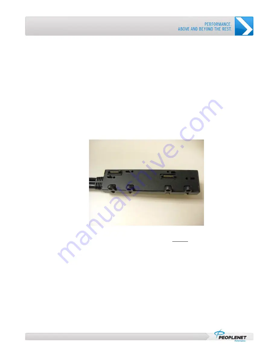
(Part # L-016-0512) Shown in Figure 4 to the back of the BLU2 device 

using the provided 8 screws (4 long and 4 short). 


Figure 4: BLU2 Cable Assembly 

2.  Determine a physical mounting location for the 

BLU2 device

 that 

will not


  Impede the driver’s vision, or 

  Cause damage to the truck from the weight of the device. 

3.  Secure one of the 

RAM Ball Mounts 

to the truck dash, if this truck already has a RAM mount for a LCD 

unit, the same mount can be used and this step can be skipped.  If this truck was equipped with a BLU 

unit and you would possibly like to reinstall the BLU unit at the end of the Beta period, remove the thumb 

screws on the sides of the BLU unit, unplug the BLU, and remove.  The Ram Ball Mount can be secured 

to the inside of the BLU Bracket using existing holes and bolts/nuts (not provided in kit.) 

4.  Verify that  the 

RAM Ball Mount

 is securely mounted. 

5.  Attach the other 

RAM Ball Mount 

to the back of the 

BLU2 device

 with the provided machine screws 

(Silver). 

6.  Attach the 

RAM Mount Arm

 to both of the ball mounts and tighten. 

The 

BLU2 device

 is now mounted. 

Содержание eDriver Logs BLU.2

Страница 1: ...Optional Image BLU2 Installation Guide Version 1 1 A guide for BLU2 installations ...

Страница 2: ...2 Installation 10 Mounting the BLU2 Device 10 DC DC Installation 11 Connecting the DC DC Power Supply to the PeopleNet System 11 Mounting the DC DC Power Supply 13 Connecting OBC G3 to the BLU2 unit 14 Plugging in the Keyboard 15 FIRMWARE DOWNLOAD 17 g3 Firmware Download Process 18 SYNCHRONIZATION 19 BLU2 OBC Synchronization Process 20 Installing a BLU2 Device 20 Error Code Recovery 21 STILL HAVE ...

Страница 3: ...STALLATION MANUAL 6 FIGURE 2 THE BLU2 DEVICE 6 FIGURE 3 BLU2 INSTALL KIT 8 FIGURE 4 BLU2 CABLE ASSEMBLY 10 FIGURE 5 DC DC POWER SUPPLY AND CONNECTORS 11 FIGURE 6 GROUND AND POWER CONNECTOR 12 FIGURE 7 BLU2 OPTIONS CABLE CONNECTOR 14 FIGURE 8 USB CONNECTION WITH ELECTRICAL TAPE AND ZIP TIE 15 ...

Страница 4: ......

Страница 5: ...Before You Begin An inventory of documentation and hardware before you install a new BLU2 ...

Страница 6: ...he PeopleNet Installation Manual before proceeding with this guide These include the following three procedures Mounting the g3 onboard computer OBC Mounting and connecting antennas Connecting the Main Cable to the OBC and the vehicle s power source Figure 1 PeopleNet Installation Manual BLU2 This is the BLU2 device shown in Figure 2 Figure 2 The BLU2 device Part M 010 0507 ...

Страница 7: ...d on the next page Qty Part Description Part 1 DC DC Supply E 006 0506 1 Cable DC DC USB Audio L 016 0512 1 Cable DC DC G3 Power L 016 0513 2 Alcohol Cleaning Pad F 004 0002 1 Black Screws H 048 0001 1 Machine Screw Pack 1 Ram Swivel Mount W 2 Bases H 050 0013 4 Hook and Loop Fasteners L 020 0020 1 Screws for mounting cable assembly to BLU2 unit 1 15 Amp fuse and holder Part M 010 0508 ...

Страница 8: ...erved Figure 3 BLU2 Install Kit Additional Parts In addition to the parts listed above you will need the following parts Additional Parts Zip ties to secure excess cabling 2 screws to mount the power supply 1 butt connector to attach the fuse holder Electrical tape ...

Страница 9: ...Installation Installation instructions for the BLU2 and related hardware ...

Страница 10: ...Figure 4 BLU2 Cable Assembly 2 Determine a physical mounting location for the BLU2 device that will not Impede the driver s vision or Cause damage to the truck from the weight of the device 3 Secure one of the RAM Ball Mounts to the truck dash if this truck already has a RAM mount for a LCD unit the same mount can be used and this step can be skipped If this truck was equipped with a BLU unit and ...

Страница 11: ...n Connecting the DC DC Power Supply to the PeopleNet System 1 Connect the DC DC Power Supply by inserting the 8 Pin and 4Pin connectors into the corresponding ports on either end of the device Connectors and DC DC Power Supply are shown in Figure 5 Figure 5 DC DC Power supply and connectors ...

Страница 12: ...factory pre wired trucks Figure 6 Ground and Power Connector 3 Using wire cutters clip off the connector and strip the ends of the wires Connect the Blue wire to vehicle ground 4 Using a butt connector connect an inline 15 AMP fuse to the Brown wire and connect to vehicle constant power Do not insert fuse at this time Wire Color Description Brown Constant 12 Volts Not Switched Blue Ground ...

Страница 13: ...Supply must be held in place by two screws If it cannot be secured by two screws zip ties or Velcro can be used to secure it to a solid object such as a support brace behind the dash Continuously cool and dry The DC DC Power Supply must be kept away from major heat sources and protected from the elements such as water 2 Mount the DC DC Power Supply in the determined location with two 2 screws Velc...

Страница 14: ...unit Connecting OBC G3 to the BLU2 unit 1 Attach the Blue options cable connector from the OBC Main Cable to the options cable connector from the BLU2 unit shown in Figure 7 Figure 7 BLU2 Options Cable Connector 2 Securely tighten the connectors together and wrap with electrical tape ...

Страница 15: ... Plugging in the Keyboard 1 Connect the USB keyboard to the USB pigtail on the BLU2 cable 2 Wrap electrical tape around the USB connection for protection and secure the USB cables with a zip tie to form strain relief loop Figure 8 USB Connection with Electrical Tape and Zip Tie ...

Страница 16: ......

Страница 17: ...Firmware Download Process for updating the g3 OBC firmware ...

Страница 18: ...will display A code mismatch is present If the OBC code is not updated the device will have limited functionality Would you like to update the OBC 2 Press Yes to continue The update process will begin and last about 7 10 minutes The screen will display OBC Firmware Updater and show the progress of the installation The update is completed when the screen displays OBC firmware upgrade successful 3 P...

Страница 19: ...Synchronization Process for activating the BLU2 and the OBC ...

Страница 20: ...d new installation and the OBC is in pending status Select No if you are replacing a LCD or BLU unit You are prompted for an Installer ID 3 Enter your Installer Number and press the Tab key or touch the Vehicle Number field to proceed You are prompted for a Vehicle Number 4 Enter your Truck Number Must be a Numeric Truck ID 5 Enter the OBC DSN 6 Press SUBMIT The activation process will proceed and...

Страница 21: ... at the bottom of the BLU2 unit 4 You may need to press the center button with a circle on it to restart the device and to reactivate the installation 5 Wait for the Process Installation screen to reappear 6 Look up your Error Code in the following table and follow the Recovery instructions Error Code Cause Recovery 1 or 4 BLU2 device not set up for a New Installation Proceed to Installing a BLU2 ...

Страница 22: ......

Страница 23: ...PeopleNet PeopleNet Canada 888 346 3486 4400 Baker Road 1100 Burloak Dr Suite 300 952 368 9320 Fax Minnetonka MN 55343 8684 Burlington Ontario L7L 6B2 info peoplenetonline com USA Canada www peoplenetonline com 2009 PeopleNet Communications Corporation All rights reserved This information is subject to change without notice ...

Отзывы: