


Technical Note
Technical Note: PendoTECH Process Control Systems: Pump Calibration
Revision 0
Page 4 of 5
Using an output that is scaled linearly assumes an ideal relationship between pump revolution and
displacement at all speeds. This is a fairly safe assumption at lower flowrates, due to limited back pressure
acting on the pump, and will generally yield stable results within 3-5% of the user entered flowrate.
However, with larger systems and higher flowrates, backpressure increases and inefficiences in the
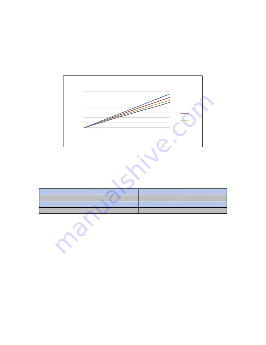
pumping mechanisms are exascerbated leading to a non-linear flowcurve. A more realistic flowcurve is
shown in the graph below. At low-moderate drive speeds the Quattroflow Q150 flowcurve is still largely
linear but as the motor speed and backpressure increase the curve begins to flatten out as the pump is no
longer operating as efficiently.
In order to compensate for the inefficiencies desribed above PendoTECH recommends conducting a flow
verification during a conditioning or flushing step. An off-line bucket check can be performed to determine
the exact flowrate being output by the system. If a retentate flow meter is in line, the permeate can be
closed and the flow meter can be used to monitor pump outptut flow. The following data demonstrates an
extreme case of non-linearity. Data provided by Triangle Process Equipment during testing of Quattroflow
Q4400 with PendoTECH TFF Process Control System.
Shaft Speed RPM HMI set point (LPM)
Actual (LPM)
Variance
215
21.66
20.7
- 4.5%
297
31
28.2
- 9%
400
40.7
37.88
- 7%
If an error of 5-10% is unacceptable by process standards than a one-point calibration can be performed to
dial in the required flowrate. This can be done by tweaking the ml/rot factor on the maintenace view sceen
as described in section 3. For example, if a 31 LPM flowrate was required, the data above shows that the
system was producing a flowrate that was 9% less than the expected value. To address this, the user could
simply decrease the ml/rot value for the circulation pump by 9% which would lead to the system delivering
exactly the required flowrate. A flowchart can be found in the appendix of this document which details how
to properly execute this procedure.
It is important to note that only the ml/rot value should be changed and not the Max RPM. If necessary this
routine can be performed for each pump operating as part of the system. In the case of the NFF, different
ml/rot values can be entered for each pump by selecting custom settings then tweaking the parameter
accordingly.
This calibration procedure is not unique to PendoTECH control system. For example, the flowrate
displayed on a Masterflex L/S during manual use is simply the pump assuming a linear flowcurve and
using the nominal values listed in section 3. The pump can then be further calibrated by the end user in
order to increase the accuracy of the system The deafult pump calibration procedure is essentially
changing the pump’s nominal mL/rotation parameter. For pumps that have an RPM display only, the user
0
0.5
1
1.5
2
2.5
3
3.5
0
500
1000
1500
2000
2500
3000
Flow
ra
te
(L/m
in
)
Pump Speed (RPM)
Quattroflow Q150 Flow Curve
0 Bar
2 Bar
4 Bar
6 Bar