


All of the configuration settings can be made through the Pelican Site Manager Web
Application. Configuration can be found under the Admin section. Each Power Module
will be listed with it's serial number and the label Power Setup.
NOTE: To assist in configuring this unit write down the Serial Number, which is found
on the front of the Wireless Control Module. Keep note of which circuit each relay is
connected to. This information will be used during the setup process.
3. Configuration
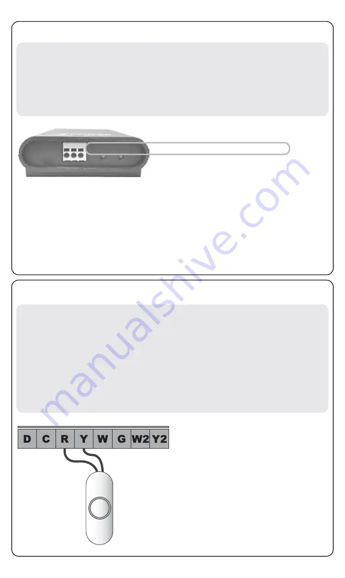
There are (5) low voltage terminals on the Power Relay Module labeled Y, W, G, W2,
Y2. These can optionally be used to manually turn relays On and Off. To use this
feature, run a two wire cable between the Power Relay Module and a momentary
pushbutton switch. Connect one wire to the "R" terminal and the other wire to the
input terminal correlating with the relay to be manually switched. Each time a one
second momentary connection is made between these two wires, the correlating dry
contact relay will change between On and Off. These manual inputs operate at
24VAC with very low current. The pushbutton switches can be located up to 500 feet
from the Power Relay Module. 18 to 24 gauge wire should be used for these
connections.
Optional: Manual Override Function
Momentary
Switch
In this configuration, pressing the momentary switch will switch
the dry contact relay labeled (Y). There is a LED light above
each relay. When the light is ON the relay is energized. When
the light is off the relay is not energized.
Diagram 4
R
STATUS
LINK
Power
Control
C
Serial: 6A3-B5DV
D
Contains FCC ID: W70MRF24J40MDME
Model: PM5
Power: 24 VAC
1. Keep track of the Serial Number.
2. Access your Pelican Web App. Select “Notifications” and select the “configure”
option next to the newly installed Power Control Module’s serial number.
4. To set relay schedules, navigate to your Pelican Web App’s home screen. Select
the relay Group and then select the calendar icon of the relay. You can schedule
the relay to turn On or Off at specific times or relative to Dusk and Dawn.
3. Each “Relay” can be uniquely named based on the load/function it will be turning
On and Off. Set unused relays to “Disabled”.


