

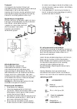


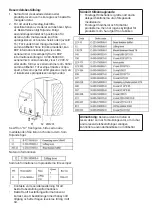

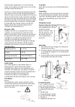


Transport
When transporting, the machine must be in its
original packaging and placed according to the
mark on the packaging. The already packed
machine must be handled with a forklift truck with
the corresponding tonnage for loading and
unloading. The location for inserting the forks is
shown in Fig. 1.
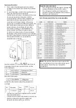
Unpacking and inspection
Peel off rivets that are attached to the pallet and
loosen the cardboard and plastic covers. Make
sure that all the parts mentioned in
the spare parts list are in the
package. If any parts are missing or
damaged, do not use the machine
but contact the distributor
immediately.
Fig 2
Fig 3
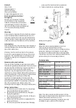
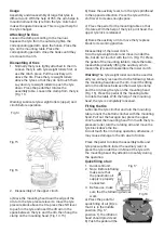
Workplace requirements
Choose a workplace in accordance with the
safety regulations. Connect the power supply and
air source according to the operating instructions.
The workplace should be well air-conditioned. For
the machine to work, it requires a workplace with
the least space on each side shown as Fig. 2. If you
install it outdoors, it must be protected with a roof
against rain and sunshine.
Warning:
Warning: The motorized machine must
not be used in an explosive area.
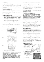
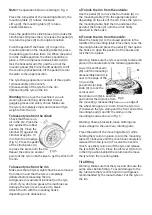
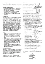
Location and installation:
1. Preparation of tools.
2. Place the swing hinges (3, Fig. 3) on the stem
(1, Fig. 3) with 4 screws (M12), thread the air
hose (2, Fig. 3) through the hole in the pillar.
Tighten 4 locknuts (8, Fig. 3).
3. Insert the bolt (9, Fig. 3) into the holes in both
the column and the inclined cylinder arm (11,
Fig. 3), tighten it with a lock nut (10, Fig. 3).
4. Unscrew the two bolts on the left cover and
remove the cover, connect the air hose (2, Fig.
3) as previously mentioned to the side holes
that guide the inclined 5-branch valve. Replace
the left cover.
5. Fasten the plastic cover (7, Fig. 3) with two
bolts (4, Fig. 3). 6) Mount the rear plastic cover
(5, Fig. 3) the column with a screw (6, Fig. 3).
Fig 4
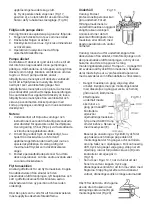
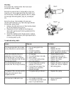
Electrical and pneumatic connections
Warning: Before mounting and connecting, make
sure that the voltage source corresponds to the
technical data of the machine. All electrical
connections must be made by a
professional electrician.
Connect the pneumatic coupling located on the
right side of the machine to the pneumatic source.
The mains to which the machine is
connected must be protected with plugs and a
proper grounding. Install the earth leakage circuit
breaker to the main power source. The firing
current must be set to 30 mA.
Warning: The machine has no plug.
The user must install a plug of more than 16 A,
which corresponds to the voltage of the machine.
Adjustment of operation
Tilt pedal (H)
Pedal of fastening
hooks
Pedal of clinch press (U)
Pedal for quick filling of air (B)
Reversing pedal of mounting
table (Z)
Содержание 507083
Страница 1: ...Tyre changer U 6656AT Däckmaskin U 6656AT en hastighet Item No 507083 ...
Страница 10: ......
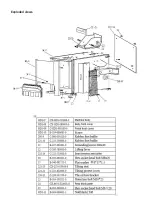
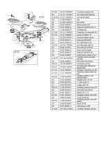
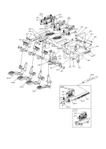
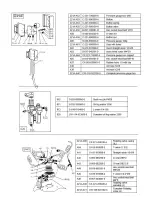
Страница 19: ...Exploded views ...
Страница 20: ......
Страница 21: ......
Страница 22: ......
Страница 23: ......
Страница 24: ......
Страница 25: ......
Страница 26: ......
Страница 27: ......
Страница 28: ......
Страница 29: ......
Страница 30: ......
Страница 31: ...Wiring diagram ...
Страница 32: ......
Страница 33: ...Verktygsboden Erfilux AB Källbäcksrydsgatan 1 SE 507 42 Borås Verktygsboden Borås Sweden 0120504 03 ...


