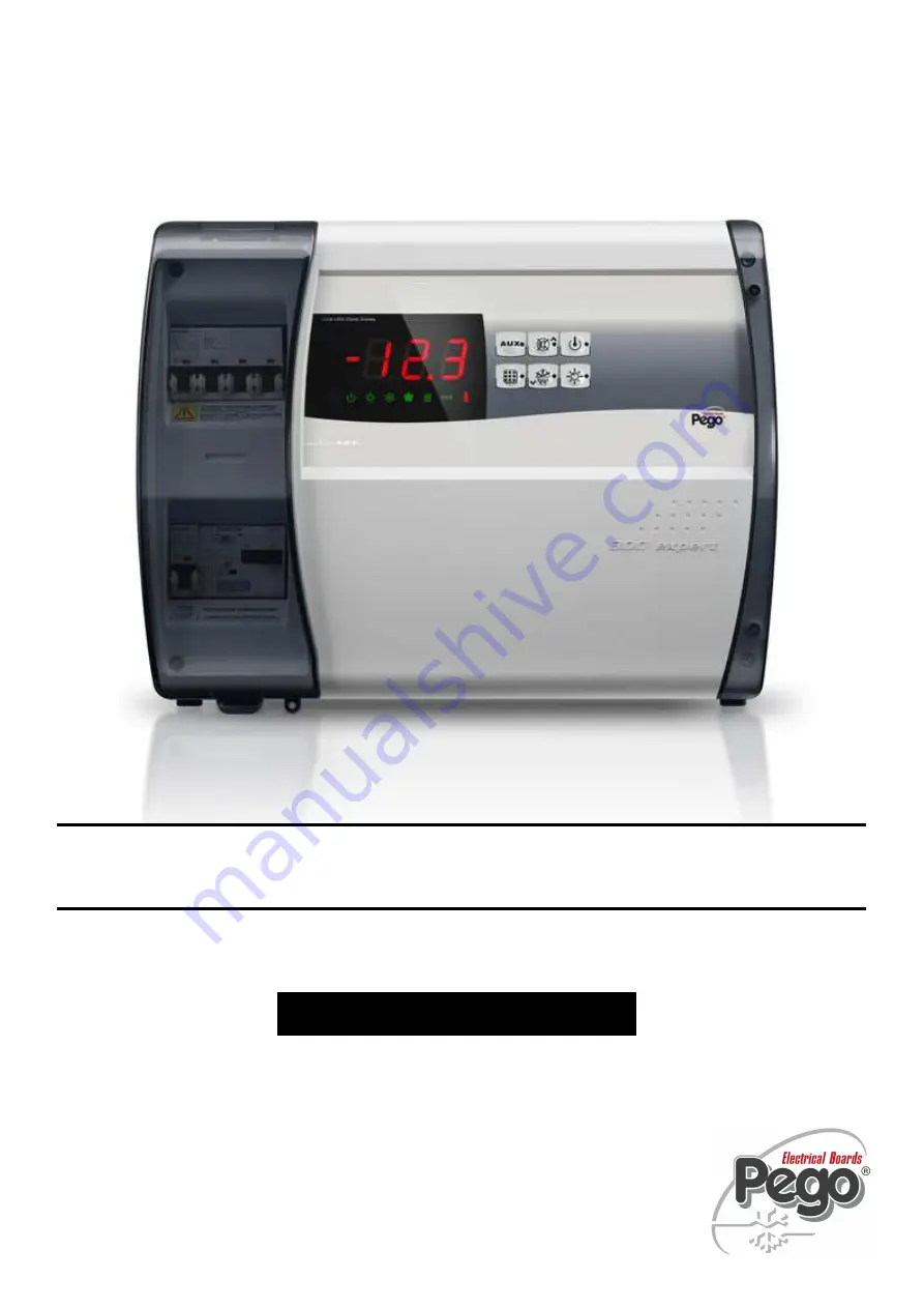
Use and maintenance manual
ELECTRICAL BOARDS FOR REFRIGERATING INSTALLATIONS
READ AND KEEP
REV. 01-12
ENG
ECP3
00
EXPERT
Страница 1: ...Use and maintenance manual ELECTRICAL BOARDS FOR REFRIGERATING INSTALLATIONS READ AND KEEP REV 01 12 ENG ECP300 EXPERT...
Страница 2: ...geration and conditioning systems A different use is allowed respecting the working conditions for which the panel is designed and made Before using the panel it s suggested to fully read this manual...
Страница 3: ...symbols Pag 25 5 6 Setting and displaying the set points Pag 26 5 7 Level 1 programming User Level Pag 27 5 8 List of Level 1 variables Pag 27 5 9 Level 2 programming Installer Level Pag 29 5 10 List...
Страница 4: ...nt of the room Different range of power combined with the various options allow the choice of an AD HOC panel for the system APPLICATIONS Complete management of three phase refrigerating systems up to...
Страница 5: ...ctrical defrost 110300EUVD01 6kW 110300EUVD02 12kW Telemecanique components PEGO identification codes Compressor motor circuit breaker range 110300EVD421 1 1 6A 110300EVD422 1 6 2 5A 110300EVD423 2 5...
Страница 6: ...GO PEGO Defrosting Electrical Electrical Status indicators LED display LED display Alarm signals LED Buzzer LED Buzzer Inputs Ambient probe NTC 10K 1 NTC 10K 1 Evaporator probe NTC 10K 1 NTC 10K 1 Doo...
Страница 7: ...A Room light protection Differential magnetothermic circuit breaker Id 30mA Differential magnetothermic circuit breaker Id 30mA Control PEGO PEGO Defrosting Electrical Electrical Status indicators LED...
Страница 8: ...ECP300 EXPERT Pag 8 USE AND MAINTENANCE MANUAL Rev 01 12 OVERALL DIMENSIONS CHAP 2 Technical characteristics 2 3...
Страница 9: ...descripted in this manual is provided on the side with a label where its identification data are written Name of Manufacturer Code and model of unit electrical board Serial number S N Power supply Au...
Страница 10: ...r free parts could be inside the panel The door is correctly closed and locked In case of not using the original package protect the product to allow transport without any damages Storage room must ha...
Страница 11: ...es repair cost will be totally at Customer charge Warranty intervention service may be refused if the device results modified or changed The Manufacturer declines every responsibility for any direct o...
Страница 12: ...a correct fixing method Install the device in places where the protection rating is observed To effect correct electrical connection and maintain the protection rating use appropriate cable glands and...
Страница 13: ...TENANCE MANUAL Rev 01 12 Fig 1 Pull up transparent cover protecting the general magnetothermic circuit breaker Fig 2 Remove screw cover on the right hand side Fig 3 Undo the 4 fixing screws at the fro...
Страница 14: ...arent protection cover Fig 5 Open the front of the box lift it and slide the two hinges out as far as they will go Fig 6 Bend the hinges and rotate the front panel by 180 downward to get access inside...
Страница 15: ...the hinges to remove them from their seats and so completely remove the front panel Fig 8 Press with a screwdriver on the 4 preimpressed holes on the bottom to prepare fixing of the panel Fig 9 Using...
Страница 16: ...previous point fix the bottom with 4 screws of a length suitable for the thickness of the wall to which the panel will be attached Fit a o ring supplied between each screw and the box backing Fig 11...
Страница 17: ...g probes sensors and digital inputs Minimise the length of connector wires so that wiring does not twist into a spiral shape as this could have negative effects on the electronics When it is necessary...
Страница 18: ...nd rotate the front panel downwards 180 to gain access inside the panel and then reconnect the electronic card connector Fig 13 In case panel is connected with TeleNET or Alarm Aux relay is used wirin...
Страница 19: ...r circuit breaker if present dedicated to the compressor as indicated in the next chapter After powering the electrical panel please check the correct current absorption on the loads and after few hou...
Страница 20: ...breaker on the compressor power circuits Using an ammeter verify the effective absorption Fig 13 Make the motor circuit breaker calibration basing on the measured absorption Any way the set up value m...
Страница 21: ...Close the front panel making sure that all the wires are inside the box and that the box seal sits in its seat properly Fig 16 Tighten the front panel using the 4 screws making sure the O rings on the...
Страница 22: ...static heating element Direct or pump down control of motor compressor unit selectable by terminal block connection in preset models Room light activation via panel key or door switch Auxiliary relay...
Страница 23: ...Y CONTROL on the version with alarm relay manually controls the relay if parameter AU 1 2 key UP MUTE WARNING BUZZER 3 key STAND BY if the system shuts down the LED flashes 4 key room temperature SETT...
Страница 24: ...DISPLAY 1 Cold room temperature parameters 2 Stand by flashes on stand by Outputs are deactivated 3 Room light flashes if door switch activated 4 Cold indicates activation of compressor 5 Fans 6 Defro...
Страница 25: ...l 2 programming directly from Level 1 you must exit the programming mode first KEY TO SYMBOLS For purposes of practicality the following symbols are used t the UP key is used to increase values and mu...
Страница 26: ...and u keys 3 Select the variable to be modified using the t or u key 4 When the variable has been selected it is possible to display the setting by pressing SET key to modify the setting by pressing t...
Страница 27: ...fter defrost minutes Allows fans to be kept at standstill for a time F5 after dripping This time begins at the end of dripping If no dripping has been set the fan pause starts directly at the end of d...
Страница 28: ...ES Installer Level VARIABLES MEANING VALUES DEFAULT AC Door switch status 0 normally open 1 normally closed 0 F3 Fan status with compressor off 0 Fans run continuously 1 Fans only run when compressor...
Страница 29: ...ary alarm relay control only on version with relay fitted 0 alarm relay 1 manual auxiliary relay controlled via AUX key 2 automatic auxiliary relay managed by StA temp setting with 2 C differential 3...
Страница 30: ...fferential r0 it deactivates the compressor when cold room temperature is lower than the setting Nel caso venga selezionata la funzione Pump down fare riferimento al capitolo 5 14 per le condizioni di...
Страница 31: ...because PUMP DOWN function is made electromechanically inside the panel PASSWORD FUNCTION When parameter PA is setting with value different to 0 the protection function is activated See parameter P1...
Страница 32: ...NING During configuration at entry Module to select the entry Instrument ECP Base Series ECP Expert Series NET CONFIGURATION WITH MODBUS RTU PROTOCOL For RS485 connections with Modbus RTU protocol to...
Страница 33: ...CE MANUAL Rev 01 12 TeleNET Alarm AUX RELAY SWITCHING Fig 18 Open the front panel as described in Chap 3 2 page 13 Fig 19 Bend the hinges and rotate front panel downwards 180 to gain access to the ele...
Страница 34: ...T Pag 34 USE AND MAINTENANCE MANUAL Rev 01 12 Fig 20 Undo the 6 CPU board cover fixing screws remove the board from the frontal part of the box in ABS Fig 21 Remove the jumper from JUMPER JP2 CHAP 6 O...
Страница 35: ...arm AUX relay Selection Insert the jumper in JUMPER JP2 in position 2 1 and set level 2 variable AU with one of the values 1 2 5 according with the desired function Terminal blocks for free voltage co...
Страница 36: ...back on E8 Man in cold room alarm Reset the alarm input inside the cold room Ec Compressor protection tripped e g thermal protection All outputs except the alarm one where applicable are deactivated C...
Страница 37: ...Reinsert then magnetothermic circuit breaker verifying all the absorptions to identify any anomalies Circuit protection fuse on the transformer intervention Restore the fuse Fusibile vetro 10X20 F250m...
Страница 38: ...s indicating maintenaince in progress Before proceeding with maintenance operations please follow these security prescriptions The electrical panel must be without voltage Prevent the presence of unau...
Страница 39: ...zed technical staff respecting the general security rules DEVICE TYPE OF INTERVENTION FREQUENCY Terminal block Wires tightening After first 20 days of functioning Terminal block Wires tightening Annua...
Страница 40: ...tibility EMC EC 2004 108 LA CONFORMITA PRESCRITTA DALLA DIRETTIVA E GARANTITA DALL ADEMPIMENTO A TUTTI GLI EFFETTI DELLE SEGUENTI NORME comprese tutte le modifiche THE CONFORMITY WITH THE REQUIREMENTS...
Страница 41: ...ase select AUX Alarm relay function by JP2 jumper and level 2 parameter AU as indicated on chapter 6 Remember then to assign a LAN address compatible with existing TeleNET network if present Level 2 p...
Страница 42: ...opening hinges 7 Front cover in transparent polycarbonate 8 Transparent polycarbonate screw cover 9 Auxiliary circuits transformer N B with inside a glass fuse 10X20 F250mA 250V 10 Connector for linki...
Страница 43: ...ECP300 EXPERT Pag 43 USE AND MAINTENANCE MANUAL Rev 01 12 NOTE...
Страница 44: ...Via Piacentina 6 b 45030 Occhiobello Rovigo Italy Tel 39 0425 762906 Fax 39 0425 762905 www pego it e mail info pego it Distributore PEGO S r l reserves the right to modify this user manual as it deem...