Peerless Pump LG Series Скачать руководство пользователя страница 10

4. Using an Allen wrench, loosen the pump coupling   
(23) set screw (38) and remove the coupling, thrust 
collars and bail bearings (14). 
 
5. Remove pump strainer (15) and suction plate (7). 


Use  care  when  withdrawing  shaft to  

                         prevent  bending  or  damage.  Use 
proper support and two men for removal of long, 
heavy shaft. 
 

6. Pull out impeller and shaft assembly (1 and 2)       
from impeller end of pump. 
 
7. Unscrew  impeller  nut  (40)  and remove washer (39). 
 
8. Remove the discharge pipe set screw (36), and      
pull the discharge pipe (12) up out of the pump 
discharge casing (6). The bottom end of the 


discharge pipe is not fastened in any way; it has a 
flexible connection sealed by a rubber packing ring    
(13). 
 
9. If pump has intermediate bearings (3) which need 
replacing, separate the hanger pipes (10). 
 

CLEANING:  
 

Pump parts may be cleaned with petroleum base 


solvent if desired. Metal parts (except motor) may be 
soaked in solvent if necessary. Use a bristle brush     
(not metal or wire) to remove tightly adhering 


deposits. Wipe the exterior of motor housing with a 
solvent-dampened cloth. Blow parts dry with clean,     
dry, compressed air. Clean ball bearings in the 


following manner: 


       Petroleum     base     cleaning     sol-      

                            vents  are  flammable.  Open  flame   
or smoking by personnel in the vicinity of these 
solvents is extremely hazardous and must not be 
permitted. Disregard of this Warning can result in 
serious bodily harm and could be fatal. 
 

1. Place bearings in wire basket – so there is space      
for cleaner to reach all parts. 


2. Immerse in Stoddard solvent. Agitate  basket  until     
old grease is thoroughly loosened and can be flushed 
out. 
 
3. Place bearing on a screened surface. 
 
4. Using a spray gun with air filter and clean 


Stoddard solvent, flush each bearing until all grease    
and sludge is removed.  


                          Never spin ball bearings. Spin- 

                            ning 

dry 

ball 

bearing 

can       

cause damage. Spinning any ball bearing by an air 
blast can cause bearing to fly apart resulting in 
possible fatal injury.  

5. Blow solvent out of bearing with dry, filtered air. 
 
6.  Lubricate  bearings  immediately  after  cleansing       
with light spindle oil and place them in a covered 
container.  
 

INSPECTION: 

Inspect pump parts for cracks, dents, 

nicks, scratches or other damage affecting service-  
ability or sealing. 

CAUTION 

 
Test cleaned and oiled bearings by rotating slowly     
with  the  hands.  If  worn,  rough,  noisy,  loose  or             
flatted, replace with new. Do not unwrap new 


bearings until ready to be installed. 
 

REPAIR: 

Remove  burrs,  nicks  or  scratches  from       

non-critical  surfaces  with  a  fine  stone  or  crocus         
cloth. 
 
Replace all parts that show wear. 
 
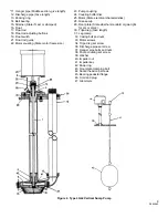
When ordering replacement parts always furnish data 
stamped  on  nameplate  attached  to  the  pump.  Give      
the figure number, index number and part name as 
shown on figure 2. 
 

TO REPLACE GUIDE BEARINGS [3, 4, and 5]: 

All 

guide  bearing  are  originally  pressed  in  at  the         
factory, being held in place by the tight fit. To 


remove the worn bearings they may either be sawed     
in half with a steel hack saw blade and collapsed, or 
threaded with a 3/4  inch tap and removed with a 3/4 
inch bolt shouldered over a pipe sleeve. 
 
New guide bearings should be pressed or lightly 


tapped in place using a block of wood as a buffer. 
 
When installing the bottom bearing (5) in pump 
discharge  casing,  be  sure  that  the  end  of  bearing           
nearer the impeller is approximately 1/8 inch within     
the housing so that the snap ring (42) on the shaft       
will not come in contact with the bearing. 

WARNING 


 Refer  motor  to  a repair shop author- 

                         Ized  by  the  motor  manufacturer  for 
repairs. It is not recommended tat user attempt to 
make repairs on this type motor under any 
circumstances.  Attempt to repair motor by unauth-
orized personnel voids manufacturer’s warranty. 

CAUTION

 
ASSEMBLY: 

To assemble the pump, reverse the 

disassembly procedure but observe the following 
precautions: 
 
1. Be sure not metal filings or cuttings are left in the 
hanger pipe. Flush out well with solvent before 


inserting shaft. 

WARNING 

 
2. Before reinstalling, clean the radial thrust bearing 
collars thoroughly in solvent. Be sure the collars are 
placed above and below the ball bearing. 

10 

2899982 

Содержание LG Series

Страница 1: ...outside the Seller s factory without prior written approval Seller makes no warranty as to starting equipment electrical apparatus or other material not of its manufacture since the same are usually covered by warranties of the respective manufacturers thereof the manufacturer and may also result in bodily injury as well as property damage This book is intended to be a permanent part of your pump ...

Страница 2: ...r manufacturer s instructions for proper wiring changes Do not cut splice or damage the power cord Do not carry or suspend the pump by the power cord A live damaged or open power cord can deliver a fatal electrical shock Due to automatic switch operation of sump pumps tie the main disconnect switch open or remove fuses from main lines before attempting lubrication mechanical and electrical examina...

Страница 3: ...inimum basin depth shown LGB furnished in 3 5 and 7 foot nominal pump lengths each suitable down to the minimum basin depths shown by adjusting floor plate 2 Gastight floor plates are required by some local plumbing codes or whenever the prevention of objection able odors entering the pump room is required Available only on LGB and LGL2 models 3 NEMA 1 simplex standard float switches are motor ped...

Страница 4: ...e and vent the basin to the atmosphere using the vent opening provided in the floor plate Mounting the Floor Plate The floor plate is fixed in location on LGA and LGL2 models On the LGB units the floor plate is furnished in two pieces marked left and right which are held together by a bolt and nut and carefully manufactured unit It should be given the same attention accorded to any precision machi...

Страница 5: ...d and are provided with cords and standard plugs for connection to any socket But the line used must have the proper electrical characteristics and be provided with the proper fuse In the event that this line is used for other appliances or for lighting a special fuse serving only the sump pump should be incorporated in the line CAUTON Before attempting hook up handling or repair of electrical wir...

Страница 6: ...h INSPECTION To insure the best operation of the unit make a systematic inspection at least once a week Watch the following grade of a No 2 or 3 grease and turn the cup down two or three turns approximately every week or two frequency depending upon severity of pump service MOTOR LUBRICATION Lubricate the motor accord ing to directions given by the motor instruction label but avoid over lubricatio...

Страница 7: ...pect bearings for wear see if strainer is clogged 3 If the flexible coupling connection is noisy see that coupling is not binding and that motor alignment is correct 4 Rotate pump by hand to see if impeller is rubbing IF PUMP OPERATES AT BLOW OR VARIABLE SPEED 1 See that switch contacts are not arcing 2 Test for loose connections 3 If motor is three phase see that all phases are live 4 Be sure the...

Страница 8: ...Figure 2 Type LG Vertical Sump Pump 8 2899982 ...

Страница 9: ...Float rod 30 Tripod leg Give length 18 Float rod adjusting buttons 31 Leg clamp 19 Float switch 32 Casing bolt and nuts 21 Float rod guide 33 Motor screws 22 Motor coupling State motor frame size 34 Tripod leg set screw 36 Discharge pipe set screw 37 Hanger pipe bolts and nuts 38 Pump coupling set screw 39 Washer 40 Impeller nut 41 Impeller key 42 Snap ring 43 Floor plate clamping bolt 44 Socket h...

Страница 10: ...ow solvent out of bearing with dry filtered air 6 Lubricate bearings immediately after cleansing with light spindle oil and place them in a covered container INSPECTION Inspect pump parts for cracks dents nicks scratches or other damage affecting service ability or sealing CAUTION Test cleaned and oiled bearings by rotating slowly with the hands If worn rough noisy loose or flatted replace with ne...

Страница 11: ...t clearance between bottom of ball bearing 14 and pump pedestal 8 When clearance has been adjusted tighten pump coupling set screw 38 Place pump in a vertical position and rotate shaft by hand If impeller rubs recheck clearance setting as outlined above 5 The float is adjusted as described previously under installation NOTICE Materials of construction specifications dimensions design features and ...

Страница 12: ...Peerless Pump Company P O Box 7026 Indianapolis IN 46207 7026 Phone 317 925 9661 Fax 317 924 7388 2899982 REV 11 76 ...

Отзывы: