


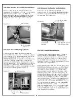


2-5 Belt Installation
Loosen the (4) bolts P#(K1191), (2) on each side, that
secure the gear box assembly to the PTO assembly
P#(A0623) (Figure 2-5a. and 2-5b.). Loosen the
adjustment bolt P#(K0348) until the gear box assembly
is at its far left adjustment (the gear box is moved toward
the mower’s engine pulley). Connect the kevlar cord belt
A61K P#(M0261) from the engine pulley to the lower
gear box pulley (Figure 2-5c.). To tension the drive belt,
turn the adjustment bolt clockwise (Figure 2-5d.) until
there is 1” of deflection, with 10-11 lbs. of pressure, at
the center of the belt between the engine pulley and the
gear box pulley. Once the correct tension of the belt is
achieved, tighten the (4) bolts that secure the gear box
assembly.
9
7
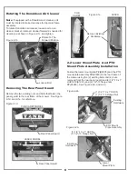
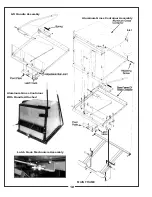
2-3 Main Frame Assembly Installation
Lift the main frame assembly P#(A0845) into position on
top of the lower mount plate and PTO mount plate
assembly. Fasten using (2) 3/8”-16 x 1” HHCS and (2)
3/8”-16 flange nuts PER SIDE. See Figure 2-3.
2-4 Universal PTO Installation
To mount the PTO assembly, insert the mount rod on the
PTO assembly P#(A0623) into the mounting slots
located on the PTO mount plate assembly P#(A0846).
Wrap the kevlar belt around both pulleys, tilt the PTO
assembly forward and insert the PTO assembly mount
pin P#(B0274) through the hole in the top of the PTO
mount plate assembly and through the PTO assembly.
Secure the PTO mount pin using 1/8” x 2-1/2” hair pin
clip P#(K0086) See Figure 2-4.
Figure 2-5a.
Figure 2-5b.
Figure 2-4.
Hair Pin Clip
PTO Mount Pin
Kevlar Belt
Figure 2-3.
Main Frame Leg
Fasten Here
Mount Plate
Loosen Bolts
Gear Box Assembly
Loosen Bolts
Adjustment
Bolt
Gear Box
PTO Mount
Plate
Figure 2-5d.
Adjustment Bolt
Engine
Pulley
Gear
Box
Pulley
Figure 2-5c.
Содержание 21621207-08
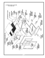
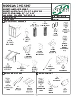
Страница 11: ...ALUMINUM GRASS CONTAINER EXPLODED VIEW 11 ...
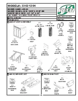
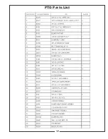
Страница 17: ...PTO Parts List 17 ...
Страница 24: ...24 ...
Страница 25: ...25 NOTES ...


