

that will attenuate the signal more
the larger the signal is, very similar
to a compressor. This is accom-
plished through the use of a spe-
cially selected dynamically resistive
light bulb. If the bulb in your Sound
Guard should ever burn out, a
replacement may be obtained from
an Authorized Peavey Service
Center. However, if a Peavey
replacement bulb is not readily
available, an automotive type 1156
bulb can be substituted for tempo-
rary use until a Peavey bulb can be
obtained.
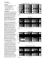
FREQUENCY RESPONSE
This measurement is useful in
determining how accurately a given
unit reproduces an input signal.
The frequency response of the SP
3G is measured at a distance of 1
meter using a 2.8 volt swept-sine
input signal. As shown in Figure 1,
the selected drivers in the SP 3G
combine to give a smooth frequency
response from 54 Hz to 17 kHz.
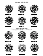
DIRECTIVITY
Beamwidth is derived from the -6 dB
points from the polar plots (see Figure 3)
which are measured in a whole space
anechoic environment. Q and Directivity
Index are plotted for the on-axis
measurement position. These are
specifications which provide a reference
to the coverage characteristics of the
unit. These parameters provide insight
for proper placement and installation in
the chosen environment. The blending of
the components of the SP 3G exhibits a
desirable beamwidth and directivity
(Figures 3 and 4) suitable for sound
reinforcement applications.
POWER HANDLING
There are many different
approaches to power handling ratings.
Peavey Electronics rates this unit's
system power handling using a
modified form of the AES Standard 2-
1984, utilizing audio band limited (20
Hz - 20 kHz) pink noise with peaks over
four times the RMS level. This
strenuous test signal assures the user
that every portion of this system can
withstand today's high-technology
music. The test signal contains large
amounts of very low-frequency energy,
effectively simulating the frequency
content of live music situations. The
full measure of high frequencies in the
test signal allow for exposure of the
speaker system to synthesized tones
that may extend beyond audibility. This
rating is contingent on having a
minimum of 3 dB of amplifier headroom
available so as to ensure that clipping
does not occur.
ARCHITECTURAL & ENGINEERING
SPECIFICATIONS
The loudspeaker system shall have
an operating bandwidth of 54 Hz to 17
kHz. The nominal output level shall be 99
dB when measured at a distance of one
meter with an input of one watt. The
nominal impedance shall be 8 ohms. The
maximum continuous power handling shall
be 350 watts, maximum program power
of 700 watts and a peak power input of at
least 1,400 watts, with minimum amplifier
headroom of 3 dB. The nominal radiation
geometry shall be 96 degrees in the
horizontal plane and 95 degrees in the
vertical plane. The outside dimensions
shall be 33.50 inches high by 21.50 inches
wide by 22.50 inches deep. The weight
shall be 95 pounds. The loudspeaker
system shall be a Peavey model SP 3G.
ONE YEAR LIMITED WARRANTY
NOTE:
For details, refer to the warranty
statement. Copies of this statement may
be obtained by contacting Peavey
Electronics Corporation, P.O. Box 2898,
Meridian, Mississippi 39302-2898.
Features and specifications subject to change without notice.
Peavey Electronics Corporation 711 A Street / Meridian, MS 39301 / U.S.A. / (601) 483-5365 / Fax 486-1278
TM
®
®
©1997
Printed in U.S.A. 5/97
80300490


