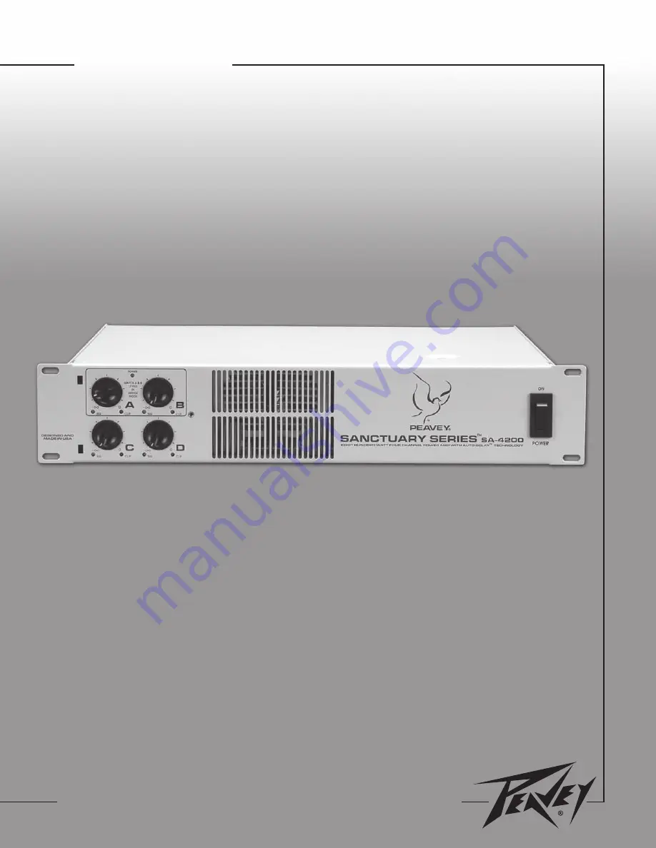
SA-4200
™
Power Amplifier Operating Guide
For information on other great Peavey products, go to your local Peavey dealer or visit us online at www.peavey.com or sanctuary-series.com
Страница 1: ...SA 4200 Power Amplifier Operating Guide For information on other great Peavey products go to your local Peavey dealer or visit us online at www peavey com or sanctuary series com ...
Страница 2: ...lisé dans ce manuel pour indiquer à l utilisateur la présence d une tension dangereuse pouvant être d amplitude suffisante pour constituer un risque de choc électrique Ce symbole est utilisé dans ce manuel pour indiquer à l utilisateur qu il ou qu elle trouvera d importantes instructions concernant l utilisation et l entretien de l appareil dans le paragraphe signalé ATTENTION Risques de choc élec...
Страница 3: ...d with the apparatus When a cart is used use caution when moving the cart apparatus combination to avoid injury from tip over 14 Unplug this apparatus during lightning storms or when unused for long periods of time 15 Refer all servicing to qualified service personnel Servicing is required when the apparatus has been damaged in any way such as power supply cord or plug is damaged liquid has been s...
Страница 4: ...stitute a claim with the carrier for damage incurred during shipping Be sure to save the carton and all packing materials Should you ever need to ship the unit back to Peavey Electronics one of its offices service centers or the supplier use only the original factory packing If the shipping carton is unavailable contact Peavey to obtain a replacement Mounting The SA 4200 amplifier will mount in st...
Страница 5: ...ity connections input cables and loudspeaker cables along with proper soldering technique to ensure trouble free operation Most intermittent problems are caused by faulty cables Consult the Wire Gauge Chart below to determine proper gauges for various load impedances and cable lengths Remember that cable impedance robs amplifier power in two ways power lost directly to resistance I2R loss and by r...
Страница 6: ...TO SUBPART J OF FCC RULES A PRODUCT OF PEAVEY ELECTRONICS CORP DESIGNED AND MADE IN U S A WWW SANCTUARY SERIES COM 120 VAC 60 Hz 1200 WATTS CLASS 2 WIRING PERMITTED FOR 70V OUTPUTS 200 WATTS CHANNEL AT 4 OR 70V OUTPUTS CLASS 3 WIRING REQUIRED FOR 140V OUTPUT BRIDGE MODE DUAL A B MODE 4 70V BRIDGE A B MODE 8 140V INPUT 1 GND 2 POS 3 NEG OUTPUT 1 GND 2 POS 3 NEG XLR DELAY FAULT CONDITIONS MOUNT IN R...
Страница 7: ...LS These controls adjust the signal level to the power amplifier inputs Maximum input sensitivity is achieved at the fully clockwise setting These controls are detented to allow the input sensitivity of the channels to be closely matched This is essential in the bridged output mode See MODE CONFIGURATION on pages 18 21 5 AC POWER SWITCH CIRCUIT BREAKER The SA 4200 amplifier has a combination AC sw...
Страница 8: ...12 FAN GRILLE A two speed DC fan supplies cool air to the amplifier This intake should never be blocked The fan automatically switches to high speed when the unit requires additional cooling When the amplifier is relatively cool and at idle the fan should operate at low speed The fan should never stop unless the amplifier is switched off or the AC mains power source is interrupted 13 CHANNEL INPUT...
Страница 9: ...EST This switch is used to activate the AUTO DELAY circuitry Before the test mode can be activated the AUTO DELAY INPUT SELECT switch 16 must be set to the desired channel and the DELAY switch 20 on that channel must be ACTIVE The Delay meter LEDs illuminate when test mode is activated The TEST REFERENCE OUTPUT 22 must be connected to the main sound system and a microphone connected to the TEST MI...
Страница 10: ...this application Phantom power 15 volts is supplied and will power most condenser microphones The test mic should be placed in the listening position nearest the auxiliary loudspeaker system that is being delayed If a directional mic is used it should be positioned so that it picks up signals from both the main and auxiliary loudspeaker systems 22 TEST REFERENCE OUTPUT This output is an electronic...
Страница 11: ...rives from the delayed loudspeaker between 1 and 30 ms after the original the delayed loudspeaker is not heard at all even if the volume from each loudspeaker is the same The sound appears to come only from the non delayed loudspeaker However the perceived volume will be louder due to the combined power of the loudspeakers He further observed that if one loudspeaker is delayed 5 to 30 ms the delay...
Страница 12: ... to manually or automatically set the delay The Auto Delay circuitry sets the delay by measuring and comparing the times for reference signals to travel to a microphone in the delayed listening position from the main and auxiliary loudspeaker systems The SA 4200 has a delay meter to indicate correct alignment of the main and auxiliary loudspeakers taking advantage of the Haas Precedent Effect Pres...
Страница 13: ... level in the room Adjust the SA 4200 amplifier channel level control on the auxiliary channel to be delayed C or D so that the volume of the tone burst in the auxiliary loudspeaker system is similar in level to the tone burst of the main system at the microphone This is not a critical adjustment Adjust the delay time using the AUTO DELAY ADJUST Control 18 on the rear of the amplifier for the prop...
Страница 14: ... Pin 3 is negative Normally balanced inputs are wired using two conductor shielded cable as shown in the following diagram For unbalanced single ended input the single conductor is wired to Pin 2 and the shield in connected to Pins 1 and 3 as shown below INPUT CONNECTIONS Balanced Unbalanced Ground Shield 1 3 2 2 3 1 LEVEL CONTROLS DETENT ATTENUATION 0 fully CCW 85 0 1 58 0 2 35 0 3 26 0 4 20 0 5 ...
Страница 15: ...amplified signal at the output of channel A Likewise a signal at the input of channel B produces an amplified signal at the output of channel B and so on The loudspeaker load is connected to the amplifier output terminals matching the positive loudspeaker connection with the positive output terminal Likewise the negative loudspeaker connection is matched with the negative output terminal See OUTPU...
Страница 16: ...nce in Bridge Mode is 8 ohms this is equivalent to driving both bridged channels at 4 ohms Using the 70V output configuration the bridged output is 140V and the minimum nominal load impedance in Bridge Mode is 50 ohms this is equivalent to driving both bridged channels at 25 ohms Driving loads of lesser impedance may activate the protective muting system See OUTPUT MODES below NOTE Regardless of o...
Страница 17: ... 70V OUTPUTS C D OUTPUT MODE SELECT OUTPUTS A B DUAL A B MODE 4 70V BRIDGE A B MODE8 140V All outputs in Low Z mode 70V Mode This mode allows each output of the channel pair to directly drive a 70 volt constant voltage audio distribution system Use Bridge Mode to deliver the power of both channels to a 140 volt constant voltage audio distribution system See INPUT MODES above LOW Z 70V OUTPUTS C D ...
Страница 18: ...se of a 70 volt matching transformer is possible with a 140 volt system by connecting the tap that is rated for 1 4 power or less to the desired 70 volt tap For example a ceiling loudspeaker with a 70 volt input tapped for 20 watts is to be used with a 140 volt constant voltage system The 140 volt system will need to be connected to the 5 watt tap in order for the loudspeaker to produce 20 watts I...
Страница 19: ...19 SA 4200 Block Diagram ...
Страница 20: ...ohms Frequency Response 0 1dB 1 Watt 10 Hz 35 kHz 80 Hz 30 kHz 0 3dB Full Power 18 Hz 30 kHz 60Hz 15 kHz with 60 Hz low cut engaged THD at rated power 1 kHz 0 05 0 05 IMD SMPTE 0 10 0 10 Damping Factor 140 8 ohms 400 Input CMRR 60 dB typ 60 dB typ Voltage Gain x20 26 dB typ x50 34 dB typ Input Sensitivity 1 42V 4 ohms 1 62V 8 ohms 1 42V Input Impedance 20k ohms balanced 10k ohms unbalanced 20k ohm...
Страница 21: ... 1500 BTU hr 8 ohms 2080 BTU hr Controls Front 4 channel input signal attenuators AC switch Rear 2 output mode switches Ch A B bridge switch HPF switches AUTO DELAY bypass switches AUTO DELAY setup switches Indicator LEDs Front 4 Clip 4 Signal 1 Power Rear 3 AUTO DELAY setup Protection Over Temperature DC turn on off transients subsonic incorrect load short circuit Connectors Input Four female XLR...
Страница 22: ...ng depth 16 63 42 24 cm behind front rack ears Weight 40 lbs 18 1 kg Power Requirements 100 120 230 240 Vac 50 60 Hz 1200 watts Test Conditions 120Vac 60Hz line input voltage maintained All channels operating unless otherwise noted Due to our efforts for constant improvements features and specifications listed herein are subject to change without notice SA 4200 4 Channel Power Amplifier SPECIFICAT...
Страница 23: ...ill pay the return shipping charges How To Get Warranty Service 1 Take the defective item and your sales receipt or other proof of date of purchase to your Authorized Peavey Dealer or Authorized Peavey Service Center OR 2 Ship the defective item prepaid to Peavey Electronics Corporation International Service Center 412 Highway 11 80 East Meridian MS 39301 or Peavey Canada Ltd 95 Shields Court Mark...
Страница 24: ...Features and specifications subject to change without notice Peavey Electronics Corporation 711 A Street Meridian MS 39301 601 483 5365 FAX 601 486 1278 www sanctuary series com 80307155 2005 ...