background image

QF

 Series

Graphic Equalizers

Thank you for purchasing a Peavey Electronics QF Series graphic equalizer. The QF family features one dual-channel 
model and one single-channel unit, all incorporating Peavey’s legendary low-noise, low-distortion design. Ruggedly 
constructed, QF Series EQs have 45 mm, center-detented control sliders enclosed in metal for durability. These two 
rack-space units also offer ±15 dB gain control and an LED display indicating output level. Other shared features include 
switchable low-cut filters, +21 dBu balanced inputs and outputs, and bypass switches. QF Series equalizer filters are 
set at ISO center frequencies within 3% accuracy. Whether on stage, in the studio, or simply tweaking your home hi-fi 
system, the QF Series has an EQ for you.

Please read this guide carefully to ensure your personal safety as well as the safety of your equipment.

Features

QF 215

•  Dual channel (15 bands per channel)
•  2/3 octave filter sets
•  ISO center frequencies within 3% accuracy
•  25 Hz to 16 kHz effective equalization range
•  45 mm, center-detent control sliders enclosed in metal for durability
•  Constant Q filters
• Output level LEDs (-12 to +12 dB)
•  12 dB boost/18 dB cut per band
•  18 dB per octave 40 Hz low-cut filter with status LED
•  +/-15 dB gain control
•  Improved Peavey FLS

®

 (Feedback Locating System)

• XLR and 1/4 inch TRS inputs/outputs for balanced or unbalanced operation

QF 131

• 31-band graphic EQ with +12 dB boost/-18 dB cut per band
• 1/3 octave filter sets
•  ISO center frequencies within 3% accuracy
•  45 mm, center-detent control sliders enclosed in metal for durability
• Constant Q filters
• Output level LEDs (-12 to +12 dB)
• 18 dB per octave 40 Hz low-cut filter with status LED
•  +/-15 dB gain control
• 20 Hz to 20 kHz effective equalization range
• XLR and 1/4" TRS inputs/outputs for balanced or unbalanced operation
• Bypass switch with status LED
• Improved FLS

®

 (Feedback Locating System) circuitry for greater sensitivity

ENGLISH

Содержание QF 151

Страница 1: ...www peavey com Operating Manual QF 231 QF 151 Graphic Equalizers ...

Страница 2: ...rée par l utilisateur Confiez I entretien et la réparation de l appareil à un réparateur Peavey agréé AVIS Dans le but de reduire les risques d incendie ou de decharge electrique cet appareil ne doit pas etre expose a la pluie ou a l humidite et aucun objet rempli de liquide tel qu un vase ne doit etre pose sur celui ci Avant d utiliser de cet appareil lisez attentivement le guide fonctionnant pou...

Страница 3: ...ack rear support should be provided 17 Note for UK only If the colors of the wires in the mains lead of this unit do not correspond with the terminals in your plug proceed as follows a The wire that is colored green and yellow must be connected to the terminal that is marked by the letter E the earth symbol colored green or colored green and yellow b The wire that is colored blue must be connected...

Страница 4: ...te verwijdering van dit product Deze markering geeft aan dat dit product nergens in de Europese Unie met ander huishoudelijk afval mag worden afgevoerd Om mogelijke schade aan het milieu of gezondheid door ongecontroleerde afvalverwijdering te voorkomen recycle het op een verantwoorde wijze om het duurzame hergebruik van materiaalgrondstoffen te bevorderen Om uw gebruikte apparaat in te leveren ku...

Страница 5: ...and 2 this device must accept any interference received including interference that may cause undesired operation Warning Changes or modifications to the equipment not approved by Peavey Electronics Corp can void the user s authority to use the equipment Peavey Electronics Corporation 5022 Hartley Peavey Drive Meridian MS 39305 601 483 5365 FAX 601 486 1278 www peavey com 2012 ...

Страница 6: ... equipment Features QF 215 Dual channel 15 bands per channel 2 3 octave filter sets ISO center frequencies within 3 accuracy 25 Hz to 16 kHz effective equalization range 45 mm center detent control sliders enclosed in metal for durability Constant Q filters Output level LEDs 12 to 12 dB 12 dB boost 18 dB cut per band 18 dB per octave 40 Hz low cut filter with status LED 15 dB gain control Improved...

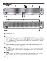
Страница 7: ...ols adjust the amount of cut or boost at their respective frequencies They are adjustable from 18 dB cut to 12 dB boost For units equipped with FLS the LED at the top of each band will illuminate as an indication of feedback at that frequency Low cut filter This switch activates the low cut filter that rejects frequencies below 40 Hz Frequency roll off is 24 dB per octave with the switch engaged T...

Страница 8: ...g proceed as follows 1 The wire that is colored green and yellow must be connected to the terminal that is marked by the letter E the earth symbol colored green or colored green and yellow 2 The wire that is colored blue must be connected to the terminal that is marked with the letter N or the color black 3 The wire that is colored brown must be connected to the terminal that is marked with the le...

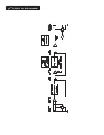
Страница 9: ...QF Series Block Diagram ...

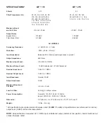
Страница 10: ...e 660 ohms Maximum Input Level 18 dBV 8 V RMS Maximum Output Level 18 dBV unbalanced 21 dBV balanced Nominal Input Level 0 dBV 1 V RMS Nominal Output Level 0 dBV 1 V RMS Input Headroom Nominal 18 dB Output Headroom 18 dB Maximum Boost and Cut Gain 15 dB 15 dB Low Cut Filter 40 Hz 24 dB per octave Power Consumption Domestic 120 VAC 60 Hz 12 Watts Export 220 230V 50 60 Hz 12 Watts Dimension 3 5 89 m...

Отзывы: