The warranty covers only the replacement and the
repair of the defective parts of the goods (recognized
by the manufacturer).
The Warranty will not be considered in the following cases:
- Whenever the use of the device does not conform to the
instructions and information described in this manual.
- In case of changes or variations made without authorization of
the manufacturer.
- In case of technical interventions executed by a nonauthorized
personnel.
- In case of failing to carry out adequate maintenance.
1.4. Technical assistance
Any further information about the documentation, technical
assistance and spare parts, shall be requested to the:
manufacturer (paragraph 1.2).
2. TECHNICAL DESCRIPTION
Close-coupled self-priming shallow well jet pumps with built-in
ejector.
JCC: version with pump casing in cast iron.
JSC: version with pump casing in stainless steel (AISI 304).
2.1. Intended use
For water and other clean liquids which are nonaggressive for the
pump materials; for slightly dirty surface water.
Liquid temperature from 32 °F to + 95 °F.
2.2. Improper use
The device is designed and built only for the purpose described
in paragraph 2.1.
Improper use of the device is forbidden, as is use
under conditions other than those indicated in these
instructions.
Improper use of the product reduces the safety and the efficiency
of the device, the manufacturer shall not be responsible for
failure or accident due to improper use.
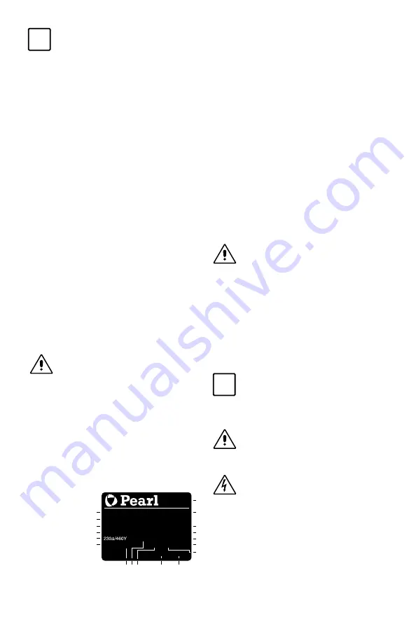
2.3. Marking
The following picture is a copy of the name-plate that is on the
external case of the pump.
3. TECHNICAL FEATURES
3.1. Technical data
Dimensions and weight (see technical catalogue).
Nominal speed 3450 rpm
Protection TEFC
The electric data marked on the label are referred to the nominal
power of the motor.
Sound pressure: < 70 dB (A).
Max. starts per hour: 40 at regular intervals.
Maximum permissible pressure in the pump casing:
- 267 ft (116 PSI)
- 334 ft (145 PSI) for JCCQ15, JCCH 15, JCCH 20.
3.2. OPERATING CONDITIONS
Installation in well ventilated location protected from
the weather, with a maximum ambient temperature of
104 °F.
4. SAFETY
4.1. General provisions
Before using the product it is necessary to know all the
safety indications.
Carefully read all operating instructions and the indications
defined for the different steps: from transportation to disposal.
The specialized technicians must carefully comply with all a
pplicable standards and laws, including local regulations of the
country where the pump is sold.
The device has been built in conformity with the current safety
laws. The improper use could damage people, animals and
objects.
The manufacturer declines any liability in the event of damage
due to improper use or use under conditions other than those
indicated on the name-plate and in these instructions.
Follow the routine maintenance schedules and the
promptly replace damaged parts, this will allows the
device to work in the best conditions.
Use only original spare parts provided by the manufacturer or
from an authorized distributor.
Don’t remove or change the labels placed on the
device.
Do not start the device in case of defects or damaged parts.
Maintenance operations, requiring full or partial
disassembly of the device, must be done only after
disconnection from the supply.
4.2. Safety devices
The device has an external case that prevents any contact with
internal parts.
4.3. Residual risks
The appliance, designed for use, when used in-line with the
design and safety rules, doesn’t have residual risks.
4.4. Information and Safety signals
For this product there will not be any signals on the product.
i
OFF
ON
i
OFF
ON
i
OFF
ON
i
OFF
ON
i
OFF
ON
i
OFF
ON
1 Pump type
2 Delivery
3 Head
4 Rated power
5 Tension nominale
6 Nom. motor current
7 Ambient temperature
8 Frequence
9 Operation Duty
10 Liquid temperature
11 Service factor
12 Insulation class
13 Weight
14 Power factor
15 Rotation speed rpm
16 Protection
17 Serial number
18 Certifications
Example plate pump
XXXXXXX
Q min/max
X/X
US gpm
XXXXXXX
H max/min
X/X
ft
TEFC
n
XXXX
/min
V3~60HzP
F
X
X/X
AT amb
XX
F CONT l.cl.
X
X
lb
Tmax liq.
XX
F SF
XX
X
kW (
X
Hp) S.F.
1
2
3
4
5
6
81
01
1
18
17
16
15
14
13
12
9
7


