background image

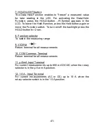
7. HOLD/LIGHT-button 
The  Data-Hold-Function  enables  to  "freeze"  a  measured  value 
for  later  reading  in  the  LCD.  For  activating  the  Data-Hold-
Function,  press  the  HOLD-

button.  „H“-Symbol  appears  in  the 

LCD. To leave the Hold-Function, press the Hold button again or 
move the Function switch. To turn on/off the backlight press the 
HOLD-button for 2 sec. 
 
8. Function selector 
To select the measuring range 
 
9. V/Ω/Hz/ 
Return terminal for all measurements 
 
10. COM Common Terminal 
Return terminal for all measurements 
 
11. µA/mA Input Terminal 
For current measurements up to 600 mA DC/AC when the rotary 
selector is in the µA or mA position. 
 
12. 10 A - Input Terminal 
For  current  measurements  (AC  or  DC)  up  to  10  A  when  the 
rotary selector switch is in the 10 A position. 


-41- 

Содержание 3410

Страница 1: ...PeakTech 3410 Bedienungsanleitung Operation manual True RMS Digital Multimeter T ...

Страница 2: ...n versorgt werden und damit einer stärkeren Blitzbeeinflussung ausgesetzt sind Hierunter fallen z B Hauptschalter am Stromeingang Überspannungsableiter Stromverbrauchszähler und Rundsteuerempfänger Zur Betriebssicherheit des Gerätes und zur Vermeidung von schweren Verletzungen durch Strom oder Spannungsüberschläge bzw Kurzschlüsse sind nachfolgend aufgeführte Sicherheitshinweise zum Betrieb des Ge...

Страница 3: ...ine Spannungsquellen über die mA A und COM Eingänge anlegen Bei Nichtbeachtung droht Verletzungsgefahr und oder die Gefahr der Beschädigung des Multimeters Der 10 A Bereich ist durch eine Sicherung abgesichert Strommessungen nur an Geräten mit entsprechender Absicherung durch Sicherungsautomaten oder Sicherungen 10 A oder 2000 VA vornehmen Bei der Widerstandsmessungen keine Spannungen anlegen Kein...

Страница 4: ...n besonders gefährliche Stromschläge auftreten Ersetzen Sie die Batterie sobald das Batteriesymbol BAT aufleuchtet Mangelnde Batterieleistung kann unpräzise Messergebnisse hervorrufen Stromschläge und körperliche Schäden können die Folge sein Sollten Sie das Gerät für einen längeren Zeitraum nicht benutzen entnehmen Sie die Batterie aus dem Batteriefach Säubern Sie das Gehäuse regelmäßig mit einem...

Страница 5: ...ung erst nach 14 Min vornehmen Der Eingang ist mit einer Sicherung 10 A 1000 V abgesichert mA Eingang für Strommessungen bis max 600 mA AC DC Der Eingang ist mit einer Sicherung 0 63 A 1000 V abgesichert max max zulässige Spannungsdifferenz von 1000 V DC AC zwischen COM Eingang und Erde aus Sicherheitsgründen nicht überschreiten max zulässige Eingangswerte 1000 V AC DC Gefährlich hohe Spannung zwi...

Страница 6: ...wertmessung 1 2 Maximal zulässige Eingangswerte Messfunktion Eingangsbuchsen max zulässige Ein gangsspannung bzw strom V DC V Hz COM 1000 V DC 750 V ACeff V AC 1000 V DC 750 V ACeff 250 V DC AC mA DC AC µA mA COM 0 63 A 1000 V DC AC 10 A DC AC 10 A COM 10 A 1000 V DC AC V Hz COM 250 V DC AC Frequenz 250 V DC AC Temperatur 250 V DC 220 V ACeff Kapazität 250 V DC AC 5 ...

Страница 7: ... nach 30 Minuten Betriebstemperatur 0 C 40 C 80 RH bereich Betriebshöhe 2000 m Lagertemperaturbereich 10 C 60 C 70 RH Temperaturbereich für 18 C 28 C 70 RH Genauigkeit Batteriezustandsanzeige Batteriesymbol Spannungsversorgung 9 V Batterie Abmessungen BxHxT 90 x 190 x 40 mm Gewicht 500 g mitgel Zubehör Prüfleitungen Batterie Temperatur fühler Temperaturadapter Be dienungsanleitung 6 ...

Страница 8: ... M 3 2 Wechselspannungsmessungen Echt Effektivwert Bereich Auflösung Genauigkeit Überspan nungsschutz 600 mV 0 1 mV 1 0 v M 5 St 1000 V AC DC 6 V 1 mV 60 V 10 mV 600 V 100 mV 750 V 1 V 1 5 v M 5 St Eingangswiderstand 10 M Frequenz 40 Hz 400 Hz 3 3 Gleichstrommessungen Bereich Auflösung Genauigkeit Überlastschutz 600 µA 0 1 µA 1 5 v M 3 St 0 63 A 1000 V 6000 µA 1 µA 60 mA 0 01 mA 600 mA 0 1 mA 6 A ...

Страница 9: ...V 6000 µA 1 µA 60 mA 0 01 mA 600 mA 0 1 mA 6 A 1 mA 10 A 1000 V 10 A 10 mA 3 0 v M 8 St 10 A Bereich Dauermessung 5 A Bei Messungen 5 A maximal 4 Minuten Nächste Messung erst nach 14 Minuten vornehmen Frequenz 40 Hz 400 Hz 3 5 Widerstandsmessung Bereich Auflösung Genauigkeit Überspan nungsschutz 600 0 1 0 5 v M 3 St 250 V DC ACeff 6 k 1 0 5 v M 2 St 60 k 10 600 k 100 6 M 1 k 60 M 10 k 1 5 v M 5 St...

Страница 10: ... mF 1 µF 5 v M 20 St 60 mF 10 µF nicht spezifiert 3 7 Diodentest Funktion Bereich Auf lösung Genauig keit Test spannung Test strom 1V 1mV 1 0 1 5V 1mA Überspannungsschutz 250V DC ACeff rms 3 8 Frequenzmessungen Logik Frequenz 1Hz 1MHz Bereich Auflösung Genauigkeit Überspan nungsschutz 99 99 Hz 0 01 Hz 0 1 v M 3 St 250V DC ACeff 999 9 Hz 0 1 Hz 9 999 kHz 0 001 kHz 99 99 kHz 0 01 kHz 999 9 kHZ 0 1 k...

Страница 11: ...9 Hz 0 1 Hz 9 999 kHz 0 001 kHz 99 99 kHz 0 01 kHz 3 9 Temperaturmessungen Bereich Auflösung Genauigkeit 55 C 0 C 0 1 C 5 0 v M 4 C 1 C 400 C 2 0 v M 3 C 401 C 1000 C 1 0 C 2 0 v M Überspannungsschutz 250 V DC 220 ACeff 3 10 Durchgangsprüfung Summer ertönt bei weniger als 30 Überlastschutz 250 V DC ACeff Leerlaufspannung 0 5 V 10 ...

Страница 12: ...3 1 2 4 11 12 8 9 10 5 6 7 13 4 Bedienelemente und Anschlüsse am Gerät 11 ...

Страница 13: ... nach 15 Minuten ohne Bedienung ab um die Batterie zu schonen 4 1 Beschreibung 1 LCD Anzeige Die LCD Anzeige dient der digitalen Messwertanzeige mit automatischer Polaritätswahl und Kommaplatzierung Die maximale Anzeige beträgt 6000 Bei Überschreitung der max Anzeigekapazität von 6000 erscheint in der Digitalanzeige das Überlaufsymbol OL 2 SELECT Taste Zum Umschalten zwischen Messfunktionen DC und...

Страница 14: ...d den REL Modus zu verlassen 5 Hz Duty Taste Bei Messungen von AC Spannungen oder Strömen ist es möglich mit der Hz Duty Taste zwischen den Messfunktionen Frequenz Arbeitszyklus oder AC Spannung bzw AC Strom ausgewählt werden Das jeweilige Messsymbol wird in der LCD Anzeige angezeigt 6 Minimal Maximalwerthaltefunktion MAX MIN Zum Ermitteln des maximalen bzw des minimalen Messwertes wie beschrieben...

Страница 15: ...s Bereichswahlschalter Zur Anwahl der gewünschten Messfunktion in die entsprechende Stellung drehen 9 V Hz Eingang Zum Anschluss der roten Prüfleitung bei Spannungs Widerstands Kapazitäts und Frequenzmessungen sowie für die Messfunktionen Diodentest Durchgangsprüfungen 10 COM Eingang Zum Anschluss der schwarzen Prüfleitung alle Messfunktionen 11 µA mA Eingang Zum Anschluss der roten Prüfleitung be...

Страница 16: ...und die beste Auflösung gewählt wird 5 Data Hold 6 Relativwert Messung 7 MAX Hold 8 MIN Hold 9 Batteriezustandsanzeige 10 Durchgangsprüfung 11 Diodentestfunktion 12 Messsymbol für Widerstands Frequenz Spannungs Strom Kapazitäts und Temperaturmessung 13 Auto Power Off Symbol zeigt aktivierte Abschaltung nach 15 min an 14 NCV Non Contact Voltage Symbol bei aktiviertem Spannungsdetektor 15 1 7 2 3 4 ...

Страница 17: ...g des Gerätes von 1000 V DC oder 1000 V AC und darf aus Sicherheitsgründen nicht überschritten werden Die maximal zulässige Spannungsdifferenz zwischen dem COM Eingang und Erde beträgt 1000 V DC AC Bei größeren Spannungsdifferenzen besteht Verletzungsgefahr durch elektrischen Schlag und oder die Gefahr der Beschädigung des Messgerätes 5 2 Universal Aufstellbügel Das Gerät ist zur Schrägstellung au...

Страница 18: ...der Messleitungen wird der richtige Messwert angezeigt WARNUNG Maximal zulässige Eingangsspannung von 1000 V DC oder 1000 V AC nicht überschreiten Bei Überschreitung besteht die Gefahr schwerer Verletzungen durch Stromschlag und oder die Gefahr der Beschädigung des Gerätes 1 Funktions Bereichswahlschalter in die für Gleich oder Wechselspannungsmessung erforderliche Stellung drehen V Bei unbekannte...

Страница 19: ... des Gerätes Zur Durchführung von Strommessungen zu messende Schaltung unterbrechen und Prüfleitungen an zwei Anschlusspunkte anlegen Niemals die Prüfleitungen parallel über eine Spannungsquelle anlegen Dies kann zu einem Ansprechen der Sicherung und Zerstörung der zu prüfenden Schaltung führen Hinweis Der maximale Eingangsstrom beträgt 600 mA oder 10 A abhängig von der benutzen Eingangsbuchse Bei...

Страница 20: ...n Wert an 6 3 Widerstandsmessungen Warnung Nach Umschaltung des Multimeters auf die Widerstands messfunktion angeschlossene Prüfleitung nicht über eine Spannungsquelle anlegen Widerstandsmessungen nur an spannungsfreien Schaltungen bzw Bauteilen vornehmen und alle Kondensatoren entladen 1 Mit dem Funktions Bereichswahlschalter die Position wählen 2 Rote Prüfleitung an den V Hz Eingang und schwarze...

Страница 21: ...Eigenwiderstand der Prüfleitungen Bei Widerstandsmessungen von 1 M und höher benötigt die Anzeige einige Sekunden zur Stabilisierung 6 4 Diodentest WARNUNG Nach Umschaltung des Multimeters auf die Diodentestfunktion angeschlossene Prüfleitungen nicht über eine Spannungsquelle anlegen Diese Funktion ermöglicht die Überprüfung von Dioden und anderen Halbleitern auf Durchlässigkeit und Kurzschlüsse E...

Страница 22: ...ge ein Wert angezeigt ist die Diode durchgängig und in Ordnung Der angezeigte Wert entspricht dem Durchlasswiderstand des Bauteils bis zu 2 0 V Wird ein Wert sowohl vor als auch nach dem Vertauschen der Polarität angezeigt ist das Bauteil kurzgeschlossen und defekt 6 5 Durchgangsprüfung 1 Funktions Bereichswahlschalter in Stellung drehen 2 Die Taste SELECT dient zur Umschaltung zwischen und 3 Rote...

Страница 23: ...n 2 Rote Prüfleitung an den V Hz Eingang und schwarze Prüfleitung an den COM Eingang anschließen 3 Prüfleitung über die zu messende Schaltung bzw das zu messende Bauteil anlegen und Frequenz in der LCD Anzeige ablesen Für genaue Frequenzmessungen wird eine Messleitung mit BNC Anschlüssen empfohlen 6 6 1 Linear Frequenzmessung Zur Messung von Sinus Netzfrequenzen gehen Sie wie folgt vor 1 Funktions...

Страница 24: ...Stellung drehen 2 Rote Prüfleitung an den V Hz Eingang und schwarze Prüfleitung an den COM Eingang anschließen 3 Legen Sie die Prüfleitungen über den zu messenden Kondensator 4 Messwert in der LCD Anzeige ablesen 6 8 Temperaturmessung Warnung Angeschlossene Prüfleitung nicht über eine Spannungsquelle anlegen 1 Funktionswahlschalter in Stellung C stellen und ggf mit der Select Taste auf F umschalte...

Страница 25: ...tärke oder dem Abstand zum elektromagnetischen Feld wird ein akustisches und visuelles Signal ausgegeben 7 Wartung des Gerätes 7 1 Auswechseln der Batterie Das Gerät erfordert eine 9 V Blockbatterie Bei ungenügender Batteriespannung leuchtet das Batteriesymbol auf Die Batterie ist dann baldmöglichst aus dem Batteriefach zu entfernen und durch eine neue Batterie zu ersetzen ACHTUNG Vor Abnahme des ...

Страница 26: ...e defekte oder verbrauchte Batterie im Messgerät belassen Auch auslaufsichere Batterien können Beschädigungen durch auslaufende Batteriechemikalien verursachen Ebenso sollte bei längerem Nichtgebrauch des Gerätes die Batterie aus dem Batteriefach entfernt werden Gesetzlich vorgeschriebene Hinweise zur Batterie verordnung Im Lieferumfang vieler Geräte befinden sich Batterien die z B zum Betrieb von...

Страница 27: ...eit 7 2 Auswechseln der Sicherung ACHTUNG Vor Abnahme der Rückwand zum Auswechseln der Sicherung Multimeter ausschalten und alle Prüfleitungen von den Eingängen abziehen Defekte Sicherung nur mit einer dem Originalwert u abmessungen entsprechenden Sicherung ersetzen F1 0 63A 1000V F 10 3 x 38 mm F2 10A 1000V F 10 3 x 38 mm ACHTUNG Die Abnahme der Rückwand und das Auswechseln der Sicherungen darf n...

Страница 28: ...en 6 Unterteil wieder auflegen und mit den 4 Schrauben befestigen Keine Messungen bei abgenommenem Gehäuse vornehmen Alle Rechte auch die der Übersetzung des Nachdruckes und der Vervielfältigung dieser Anleitung oder Teilen daraus vorbehalten Reproduktionen jeder Art Fotokopie Mikrofilm oder ein anderes Verfahren nur mit schriftlicher Genehmigung des Herausgebers gestattet Letzter Stand bei Druckl...

Страница 29: ... of persuade of a lightning i e main switches on current input overvoltage diverter current use counter To ensure safe operation of the equipment and eliminate the danger of serious injury due to short circuits arcing the following safety precautions must be observed Damages resulting from failure to observe these safety precautions are exempt from any legal claims whatever Do not use this instrum...

Страница 30: ... before connection to the equipment To avoid electric shock do not operate this product in wet or damp conditions Conduct measuring works only in dry clothing and rubber shoes i e on isolating mats Never touch the tips of the test leads or probe Comply with the warning labels and other info on the equipment The measurement instrument is not to be to operated unattended Always start with the highes...

Страница 31: ...solvents The meter is suitable for indoor use only Do not operate the meter before the cabinet has been closed and screwed safely as terminal can carry voltage Do not store the meter in a place of explosive inflammable substances Do not modify the equipment in any way Do not place the equipment face down on any table or work bench to prevent damaging the controls at the front Opening the equipment...

Страница 32: ...x current that you can measure with this terminal is 600 mA that is fuse protected by 0 63 mA 1000 V fuse max To avoid electrical shock or instrument damage do not connect the C Common Input COM terminal to any source of 1000 V DC AC with respect to earth ground The max voltage this meter can measure is 1000 V AC DC Be exceptionally careful when measuring high voltages Do not touch the terminals o...

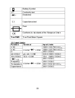
Страница 33: ...e Root Mean Square 1 2 Input Limits Function Terminal Input Limits V DC V Hz COM 1000 V DC 750 V ACrms V AC 1000 V DC 750 V ACrms 250 V DC AC mA DC AC µA mA COM 0 63 A 1000 V DC AC 10 A DC AC 10 A COM 10 A 1000 V DC AC V Hz COM 250 V DC AC Frequency 250 V DC AC Temperature 250 V DC 220 V ACrms Capacitance 250 V DC AC 32 ...

Страница 34: ...power off after 30 minutes Operating temperature 0 C 40 C 41 F 104 F 80 RH Altitude 2000 m Storage temperature 10 C 60 C 14 F 122 F 70 RH Temperature for guaranteed accuracy 18 C 28 C 70 RH Low battery indication Battery symbol Battery Type 9 V battery Dimensions WxHxD 90 x 190 x 40 mm Weight 500 g Accessories Test leads operating manual battery thermocouple multi functionadapter 33 ...

Страница 35: ...M 3 2 AC voltage measurement True RMS Range Resolution Accuracy Overload protection 600 mV 0 1 mV 1 0 rdg 5 dgt 1000 V AC DC 6 V 1 mV 60 V 10 mV 600 V 100 mV 750 V 1 V 1 5 rdg 5 dgt Input impedance 10 M Frequency 40 Hz 400 Hz 3 3 DC current measurement Range Resolution Accuracy Overload protection 600 µA 0 1 µA 1 5 rdg 3 dgt 0 63 A 1000 V 6000 µA 1 µA 60 mA 0 01 mA 600 mA 0 1 mA 6 A 1 mA 1 5 rdg 5...

Страница 36: ...60 mA 0 01 mA 600 mA 0 1 mA 6 A 1 mA 10 A 1000 V 10 A 10 mA 3 0 rdg 8 dgt 600 µA 600 mA range 10 A Range Duration measurement 5A Measurements at 5A for maximal 4 minutes on load and 14 minutes off load Frequency 40 Hz 200 Hz 3 5 Resistance Test Range Resolution Accuracy Overload protection 600 0 1 0 5 rdg 3 dgt 250 V DC ACpp 6 k 1 0 5 rdg 2 dgt 60 k 10 600 k 100 6 M 1 k 60 M 10 k 1 5 rdg 5 dgt 600...

Страница 37: ...tion Accuracy Test voltage Test current 1 V 1 mV 1 0 1 5 V 1mA Overload protection 250 V DC ACrms 3 8 Frequency Logic frequenzy 1 Hz 1 MHz Range Resolution Accuracy Overload protection 99 99 Hz 0 01 Hz 0 1 rdg 3 dgt 250V DC ACpp 999 9 Hz 0 1 Hz 9 999 kHz 0 001 kHz 99 99 kHz 0 01 kHz 999 9 kHZ 0 1 kHz Linear frequenzy 6Hz 100kHz Range Resolution Accuracy Overload protection 99 99 Hz 0 01 Hz 0 05 rd...

Страница 38: ...55 C 0 C 0 1 C 5 0 rdg 4 C 1 C 400 C 2 0 rdg 3 C 401 C 1000 C 1 0 C 2 0 rdg Overload protection 250 V DC 220 V ACrms 3 10 Continuity Test Buzzer beeps continuously at less than 30 Overload protection 250 V DC ACrms Open circuit voltage 0 5 V 37 ...

Страница 39: ...3 1 2 4 11 12 8 9 10 5 6 7 13 4 Front Panel Description 38 ...

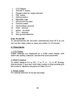
Страница 40: ...the meter automatically turns off if you do not turn the rotary switch or press any button for 15 minutes 4 1 Description 1 LCD Display Digital readings are displayed on a 6000 count display with automatic polarity indication and decimal point placement 2 SELECT button To select between AC or DC C or F or EF Energy field detector Press and hold Select button during switching on the device to disab...

Страница 41: ... measuring ac voltage or ac current you can press this button to select frequency duty cycle or ac voltage or ac current measurement function and the display will show the relevant symbol In frequency or duty cycle measurement mode you can press this button to switch between frequency and duty cycle measurements 6 Max MIN HOLD Function For measuring the MIN or Max value make the following steps Pr...

Страница 42: ... switch To turn on off the backlight press the HOLD button for 2 sec 8 Function selector To select the measuring range 9 V Ω Hz Return terminal for all measurements 10 COM Common Terminal Return terminal for all measurements 11 µA mA Input Terminal For current measurements up to 600 mA DC AC when the rotary selector is in the µA or mA position 12 10 A Input Terminal For current measurements AC or ...

Страница 43: ...e in which the meter automatically selects the range with the best resolution 5 Data Hold 6 Relative mode 7 MAX MIN Hold 8 MIN Hold 9 Low battery indicator 10 Continuity test 11 Diode test 12 Symbols for resistance frequency voltage current capacitance and temperature 13 Auto Power Off Symbol 14 NCV Non Contact Voltage finder shows during EF measurement 42 1 7 2 3 4 14 5 6 9 10 11 12 13 8 ...

Страница 44: ...ge greater than 1000 V DC AC with respect to earth ground This creates a serious shock hazard 5 2 Using the stand Use your meter s stand to prop up the meter If you prop your meter on a bench top the stand helps provide a better viewing angle To use the stand as a prop just open it away from the meter and set it on a flat surface 6 How to make measurements Understanding Phantom readings In some DC...

Страница 45: ...e black test lead into the meter s COM terminal and the red test lead into the V Hz terminal 3 Connect the test leads to the DC AC voltage source you want to measure Warning When you connect the test probes to an AC outlet do not turn the rotary selector switch to another range It could damage the meter s internal components or injure you 6 2 Measuring DC AC Current WARNINGS Do not apply voltage d...

Страница 46: ... needed to get a reading 2 Press SELECT to select between DC and AC 3 Plug the black test lead into your meter s COM terminal and the red test lead into your meter s µA mA or 10 A terminal 4 Remove power from the circuit under test and then break the circuit at the appropriate point 5 Connect the test leads in series with the circuit 6 Apply power and read the current Your meter displays the curre...

Страница 47: ...l 3 Connect the test leads to the device you want to measure Notes If the measured resistance value exceeds the maximum value of the range selected OL appears This indicates an overload Select a higher range In this mode the beeper does not sound When you short the test leads in the 600 range your meter displays a small value no more than 0 3 This value is due to your meter s and test leads intern...

Страница 48: ...s actual forward voltage up to 2 0 volts If the display still indicates an overrange condition the device is open If the display shows a value both before and after you reverse the polarity the device is shorted When you connect the diode to the meter and the meter displays the devices forward voltage the red test lead is connect to the diode s anode and the black test lead is connected to the dio...

Страница 49: ... signal that exceeds 250 V ACrms you might damage your meter and expose yourself to a severe shock hazard Follow these steps to measure the frequency of a signal 1 Set the rotary selector to Hz 3 Connect the test leads to the frequency source 6 6 1 Linear frequency measurement Proceed to measure Sine Grid frequencies as follows 1 Turn function range switch in position in V 2 Connect the red test l...

Страница 50: ...e cords 1 Set the function switch to the position 2 Plug the black test lead into yours meter s COM terminal and the red test lead into your meter s V Hz terminal 3 Set the RANGE button to the correct measuring range 4 Touch the test leads to the capacitor to be tested The display will indicate the proper decimal point value 6 8 Temperature measurements Warning To avoid electric shock disconnect b...

Страница 51: ...oved before changing to another measurement function 6 9 Non Contact Voltage tester Electric Field Detector Warning A non contact voltage search cannot replace a voltage measurement Before you touch a supposedly power free conductor make sure to test the voltage with the cable linked voltage measurement 1 Turn function range switch in V position 2 Press Select Key to switch to EF 3 Place device wi...

Страница 52: ...urn off the power and disconnect the two test leads 2 Remove the 2 screw to open the battery cover 3 Remove the battery 4 Place the battery into the insulation capsule 5 Replace the battery cover and secure it with the screws WARNING Do not operate the meter until you replace the battery and close the battery compartment cover Notes Never leave a weak or dead battery in your meter Even a leakproof...

Страница 53: ...t stamps You can obtain further information about the Battery Regulations from the Bundesministerium für Umwelt Naturschutz und Reaktorsicherheit Federal Ministry of Environment Nature Conservation and Reactor Safety 7 2 Replacing the fuse WARNING To avoid electric shock disconnect the test leads before removing the battery or the fuse Replace only with the same type of battery or fuse Service sho...

Страница 54: ... it with the screws All rights also for translation reprinting and copy of this manual or parts are reserved Reproduction of all kinds photocopy microfilm or other only by written permission of the publisher This manual considers the latest technical knowing Technical alterations reserved We herewith confirm that the units are calibrated by the factory according to the specifications as per the te...

Отзывы: