

For help locating the vehicle’s reverse light circuit, contact your vehicle’s manufacturer for
vehicle specific wiring diagrams.
10. Once you have located the reverse light circuit, you need to route the power cable supplied to
that location. Fasten the power cable securely to prevent it from being caught on any vehicle
component like the trunk hinge.
Never
route the cable on the outside of the vehicle.
11. Locate reverse light socket and remove light bulb. There are two wires connected to the
reverse light sockets on most vehicles. Usually the negative wire is black and the positive
wire is a colored wire. If you are uncertain about the wiring, use a 12 volt multimeter
(available at most auto parts stores) to determine which wire is positive. Follow the
manufacturer’s instructions for the safe use of the multimeter.
12. After determining which wire is the positive and which is the negative, turn off the ignition key,
then remove the battery’s negative cable.
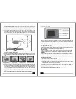
Insert the existing wire
Insert the wire to be
Crimp clamp with pliers,
to be tapped to the clamp. attached to the clamp. then close lock.
14. You may not need to use the wire clamp. The power cable can be wired directly to the reverse
light circuit by stripping the reverse light wires then twisting the camera wires to the exposed
reverse light wires. Once connected, wrap with electrical tape. Do not attempt this if you
are not knowledgeable with electrical installation practices. If in doubt, seek professional
installation assistance.
15. Next splice the black wire of the camera’s power cable to the reverse light’s negative (-) wire
or ground.
16. Replace the reverse light bulb and re-install the light socket. Secure all the wires with cable
ties or electrical tape. Reattach the negative battery cable to the battery afterwards.
Wire clamp after locking
5
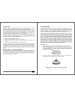
MONITOR CONTROLS
BLUE LED Power Indicator
When the monitor is ON the blue LED will be lit. If there is power to the monitor, but the monitor is
OFF, the blue LED will be OFF.
Power Button
Press the Power button to turn the display ON; the blue LED will be lit to indicate the monitor is
ON. Press it again to turn the display OFF; the blue LED will turn off.
Contrast Control
There are 1
0
levels of contrast. To adjust the contrast, press the Contrast Control button.
Pressing the button to increase the contrast at the highest level will return to the lowest level.
Brightness
There are 1
0
levels of brightness. To adjust the brightness, press the Brightness Control button.
Pressing the button to increase the brightness at the highest level will return to the lowest level.
TESTING THE SYSTEM
1. Reattach the vehicle’s negative battery cable.
2. Turn the ignition key to the accessory position; do not start the vehicle.
3. Engage the parking brake, then put the shifter in the reverse position.
4. Turn the monitor ON by pressing the ON/OFF button on the monitor.
5. Look at the monitor; if the image does not match your rear view mirror press the Image
Orientation button on the monitor to correct the image.
After testing the unit and you are satisfied with the route you have chosen for the cabling, you
must permanently install it.
Fully tighten the license plate bolts.
Route all wires behind interior panels or under carpeting so they are hidden.
Use supplied cable ties to neatly gather any excess wire.
6
13. Splice the red wire using the supplied wire clamp to the reverse light’s positive (+) wire. Use a
set of slip joint pliers to squeeze the METAL BLADE and ensure good connection of both
wires.
Make sure the monitor is powered ON (STANDBY), then the monitor will automatically show the
camera’s image when the vehicle is in reverse gear. Also, there are 4 control buttons available for
user to have their controls.


