Document Number: PD196-244R12
PD295-002
Page 14 of 29
PDi Communication Systems, Inc. 40 Greenwood Lane Springboro, Ohio 45066 USA PH 1-800-628-9870 FX 937-743-5664
TV Setup
–
A-Series
To establish communication to interface module the CCI port on the TV must be active and you must have a PDi
programming remote PD108-420 (not included).
1. From the TV, open the TV Setup Menu by pressing SETUP on the programming remote.
2. Select
“
Sources
”
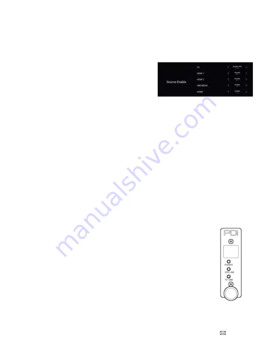
and then select “Source Enable”.
Set each item as detailed below.
The TV Source Setup must properly reflect the actual
connections to the TV. Incorrect settings will result in loss of
programming or the addition of blank signal sources. In most
installations, both cable/satellite and off-air programming is
delivered over RF so the “TV” must be enabled. If the
cable/satellite channels are delivered over an alternate
method such as HDMI, then that source must be enabled. All
unused sources should be disabled.
TV Setup
–
medTAB
medTAB14C, medTAB19C, and medTAB16C are compatible with PDi interface modules. To establish communication to
interface module the CCI port on the TV must be active. Setup on the medTAB14C and medTAB16C can be completed
with a PDi programming remote PD108-420 (not included). medTAB19C setup is completed through onscreen
touchscreen controls.
1. From the TV app, open the TV Settings Menu, by pressing SETUP on the programming remote or by pressing
Settings on the touchscreen TV controls. Enter password (
“45066”
is factory default).
2. Select
“
Advanced Option
”.
3.
Select “Features” then select “Input Sources”.
Set each item as detailed below.
The TV Source Setup must properly reflect the actual connections to the TV. Incorrect settings will result in loss
of programming or the addition of blank signal sources. In most installations, both cable/satellite and off-air
programming is delivered over RF so the “TV” must be enabled. If the cable/satellite channels are delivered over
an alternate method such as HDMI, then that source must be enabled. All unused sources should be disabled.
Verifying and Troubleshooting Connections
The following steps verify the data connections between the STB and TV. These instructions assume
you have followed the previous connection and TV setup sections of this manual.
1. Power the TV.
2. Power the set top box.
3. Power the interface module.
4. Examine the front mounted status lights on the PD295-002 interface module. It contains a Power
status light, a set top box (STB) status light and a TV status light.
a. Each light will turn green when properly connected.
b. A dark (Off) status light indicates a problem.
c. Blinking indicates data transfer.
d. All 3 lights lit indicates all connections are working properly.
NOTE: While the link lights indicate a working connection, they do not confirm the audio/video (RF or
HDMI) from the STB is connected to the correct TV. Please review t
he “Troubleshooting” section for additional help.


