Brought to you by PCS Electronics, www.pcs-electronics.com
28
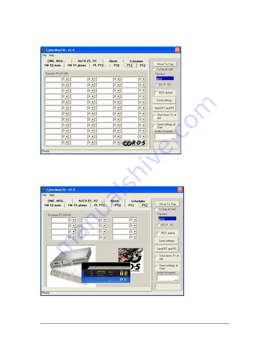
PS1
Next level of PS messages.
PS2
Last level of PS messages.
Страница 1: ...Brought to you by PCS Electronics www pcs electronics com 1 CyberMaxFM DSP RDS High performance FM radio broadcasting exciter Covers 150W 300W 500W and 750W models silver and black front panel Manual...
Страница 2: ...nd cheap locally They can be obtained in any radio computer hardware shop at the cost of about 1 US It is the type used in your PC for mains power Study local regulations and ensure you are always ope...
Страница 3: ...R CABLE 15 AUDIO SOURCE WITH MIXER MICROPHONE ETC 15 WIRING EVERYTHING TOGETHER 16 WIRING THINGS UP AND FIRST POWER UP 16 USING THE CYBERMAXFM SERIES TRANSMITTER 17 LCD CONTROL MODULE MENU SYSTEM POWE...
Страница 4: ...LTI BAY CONFIGURATIONS 40 APPENDIX C ATTACHING EXTERNAL STEREO PROCESSOR 41 APPENDIX D PC REMOTE CONTROL VIA USB AND RS232 42 SOFTWARE INSTALLATION 42 CONFIGURING COMMUNICATIONS PORT 43 INSTALLING USB...
Страница 5: ...rature They are available in mono MPX input and stereo with regular or DSP stereo encoder RDS Radio Data System option is also available Of course this unit is completely no tune and works from any ma...
Страница 6: ...dance 10Kohms balanced 1Kohms unbalanced Limiter Yes all models Pre emphasis Yes precision 50uS 75uS or none for all models DSP Yes in DSP models General Mains power 110 240V 50 60Hz universal worldwi...
Страница 7: ...nals power is ON 4 Red error led Turns on while VCO is tuning into selected frequency and in case of SWR or TEMP error 5 Power switch in the middle of the panel is actually a standby switch To really...
Страница 8: ...tilation aperture 4 Antenna connector N female Do not operate without antenna 5 BNC connectors for MPXin MPXout and 19KHz pilot 6 RS232 USB for controlling your RDS encoder and FM transmitter 7 Audio...
Страница 9: ...now going to have a look at these building blocks Fig 3 Block diagram of the CyberMaxFM transmitter Reference Function 1 Mains power supply universal input 110 240V IEC jack same as for PC 2 DC DC co...
Страница 10: ...iter board CyberMaxFM units are all based on our MAXPRO5000 series FM exciters note the current revision may differ slightly from the board in your transmitter as we are constantly fine tuning the des...
Страница 11: ...very small K RF monitor output This output contains a small sample of output signal suitable for monitoring RF signal quality with instruments such as frequency meter frequency analyzer or modulation...
Страница 12: ...SWR signal only use if you are not using digiamp connector I Y Increases sensitivity of external power and SWR meter 1 Power limit jumper J12 use to limit output power to 2 4 6 or 8W exact value depe...
Страница 13: ...discuss each of the manuals with other forum members here http www pcs electronics com phpBB2 viewforum php f 33 Ref Function J1 2 Audio Inputs J3 4 Pre emphasis selection J7 MPX out going to FM exci...
Страница 14: ...antenna came off in your hand the VSWR could be so bad as to blow the final transistor For the same reason check the DC continuity of the antenna with an ohmmeter before plugging it in to be sure it...
Страница 15: ...t probably for radio grade universal butother interpretations exist The common RG 58 from Radio Shack is NOT the best you can do and can eat a lot of your effective power out Use it only for short run...
Страница 16: ...ch is off connect mains power cable into the mains power supply and connect mains power supply into the back of the transmitter Inspect all cables quickly again and make sure everything is secure Turn...
Страница 17: ...r press on the MENU key and you re back to the normal mode Note that all these settings except power and frequency are already set as they should be so changing them should not be necessary and is not...
Страница 18: ...diagnosing mains power failures Auto Scroll D This is the default view it shows each of the above listed views for a short while and than moves on to the next in an endless loop This way you can see...
Страница 19: ...dio needs to be loud for the compressor to respond by reducing the gain This is not to be confused withattack time Attack time of 50ms means the compressor will respond in 50ms after the signal spike...
Страница 20: ...erature alarm here We recommend you set these to 75 degrees Celsius A properly installed unit with a tiny fan will typically run at 55 degrees C at maximum output power This alarm applies to externall...
Страница 21: ...ible to set a limit power level for example 500W and exciter will reduce its output power if needed to prevent overdriving This is a very useful feature when you are for example building a 500W 1000W...
Страница 22: ...Baud rate is selected automatically according to the selected FM transmitter type Communication test tool Use this feature to find correct settings easily Try different settings and check them by cli...
Страница 23: ...ur FM transmitter type FM transmitter frequency Set the frequency by 0 5 or 0 05MHz step Transmitter output power Set the desired output power Stereo Mono Select audio mode Audio input level Select au...
Страница 24: ...the decay time this is the time the compressor needs to respond after the input signal falls back to normal level below threshold Interval Set the integration interval this is the time the DSP evaluat...
Страница 25: ...alarms Here many operating parameters can be observed including alarms Threshold values of alarms can be set too Read TX Click this button to get the current status of your hardware Auto read TX Chec...
Страница 26: ...flag on even though you don t transmit any traffic announcements Program type PTY This is an identification number to be transmitted with each program item and which is intended to specify the curren...
Страница 27: ...but others don t Whatever your decision may be RDSMAX supports either static or dynamic PS It is best to check with the local authorities before setting up the RDS encoder The mechanism for handling d...
Страница 28: ...Brought to you by PCS Electronics www pcs electronics com 28 PS1 Next level of PS messages PS2 Last level of PS messages...
Страница 29: ...ize RDS RTC Real Time Clock with current PC clock External switchable messages To activate these messages attach 8 switches to header J10 EXTMSG These switches must be going to ground from each of the...
Страница 30: ...folder Install it and configure it to output winamp song info into your text file and than set RDS MAX driver to read song name from that file Also make sure you setup VtitleSpy plugin to limit song...
Страница 31: ...ht to you by PCS Electronics www pcs electronics com 31 About Firmware version Here can be found firmware version of your hardware At least one TX read must be proceeded to get the proper firmware ver...
Страница 32: ...settings to send parameter values PS00 and RT to RDS encoder Use Send RT and PS to send all PS and RT parameters to RDS encoder Shut down TX at exit Check this box to automatically reduce transmittin...
Страница 33: ...of each line to make that line active There can be many lines active if desired It is recommended to be careful while entering lines not to make time overlapping lines active at the same time Example...
Страница 34: ...ng time Daily repetition mode switches every day at the same time To make sense at least two daily based lines should be active at the same time Weekly repetition mode allows individually selection of...
Страница 35: ...WR and TEMP protection Fuse is the first thing to check Make sure your coaxial cable leading to the transmitter or antenna is not shorted or open Next check the troubleshooting table on the next page...
Страница 36: ...o open the trimmer on MAX PRO 5015 exciter board 3 Get a compressor you can t sound as loud as best commercial stations unless you get a compressor they are all using one this can either be a software...
Страница 37: ...rchasing SWR meter to tune and align your antenna A good antenna system is extremelyimportant and can make up for a lot of power For a suitable SWR meter check http www pcs electronics com cn101l daiw...
Страница 38: ...tional amplifier to boost therange Such stations can go into kilowatts but they are starting to hit another speed limit Since the studio is typically located in a town high RF powers aren t desirable...
Страница 39: ...th this antenna system and perfect coaxial cable losses 0 would have ERP of 2000W Note the antennas are mounted on the opposite sides of the pole to help make radiation pattern as omni directional as...
Страница 40: ...s made from sections of coaxial cable with such impedance and length which ensure perfect match at specific frequency Do not attempt to assemble from regular 50 ohm coaxial cable What is important her...
Страница 41: ...what your system would look like for wireless studio transmitter link Fig 23 Using external stereo rds processor for wireless link Fig 23 Using external professional stereo rds processor It is import...
Страница 42: ...Once you have the driver run the setup file and install the program on your computer This process is very straight forward and should only take a few minutes Wait for the installation to complete and...
Страница 43: ...lease set COM port to 1 or 2 These settings are usually correct If not we will explain the installation and setup process for USB control cable in more detail below You canuse Communication test tool...
Страница 44: ...ber here you will need it later to configure the COM port inside CyberMaxFM windows control program If you wish to change this port right click on the PCS USB COM port and select Properties Now select...
Страница 45: ...ation to complete and than start the program Connect the CYBERMAXFM to your network via Ethernet cable cable not included The Ethernet adapter is setup to accept IP from your router s DHCP server It i...
Страница 46: ...Brought to you by PCS Electronics www pcs electronics com 46 Fig 31 Seting up Ethernet connection for CYBERMAXFM screen 2 Fig 32 Seting up Ethernet connection for CYBERMAXFM screen 3...
Страница 47: ...Brought to you by PCS Electronics www pcs electronics com 47 Fig 33 Seting up Ethernet connection for CYBERMAXFM screen 4 Fig 34 Seting up Ethernet connection for CYBERMAXFM overview...
Страница 48: ...motorists identified in parallel with the ARI system with the corresponding RDS features TP TA But ARI is being replaced on a European scale so it will cease after the year 2005 A more recent develop...
Страница 49: ...will cache this information with the frequency and other details associated with that preset CT Clock Time Can synchronize a clock in the receiver or the main clock in a car Due to transmission vagar...
Страница 50: ...Brought to you by PCS Electronics www pcs electronics com 50 List of RDS and RBDS program type codes and their meanings...
Страница 51: ...Brought to you by PCS Electronics www pcs electronics com 51 RDS Country codes RDS TP and TA codes...
Страница 52: ...lect MSComm1 InputLen 0 MSComm1 PortOpen True General Command Format This is the format of a typical command sent to the RDSMAX encoder StartByte Command EndCommandByte Value EndByte StartByte Signals...
Страница 53: ...splayed one after the other until the entire loop repeats itself You can define how long each of these strings is displayed the parameter which defines this is PD PD00 to PD99 Example If you wish to j...
Страница 54: ...Chr 1 End command and start of data 1 temp Str TXStereo temp LTrim temp MSComm1 Output temp MSComm1 Output Chr 2 Finish command Sending RDS active PWR MSComm1 Output Chr 0 Start 0 MSComm1 Output PWR P...
Страница 55: ...Chr 2 Finish command Sending Did0 MSComm1 Output Chr 0 Start 0 MSComm1 Output Did0 MSComm1 Output Chr 1 End command and start of data 1 temp Str DId0 temp LTrim temp MSComm1 Output temp MSComm1 Output...
Страница 56: ...le MSComm1 Output Chr 0 Start 0 MSComm1 Output FDT MSComm1 Output Chr 1 End command and start of data 1 MSComm1 Output Chr Treble 4 MSComm1 Output Chr 2 Finish command Sending DSP settings Bass MSComm...
Страница 57: ...SComm1 Output Chr 1 End command and start of data 1 MSComm1 Output Chr TEMPAlarm 4 MSComm1 Output Chr 2 Finish command Sending settings SWR alarm MSComm1 Output Chr 0 Start 0 MSComm1 Output FAS MSComm...
Страница 58: ...ocking fee and your original shipping and handling charges will not be refunded The return of the product is at your expense We believe that this is a fair policy because lower overhead results in low...
Страница 59: ...fessional and hobby FM radio stations A large assortment of hard to obtain RF components RF transistors MRF 2SC coils silver platedwire coaxial cable capacitors quartz crystals and many others PC base...
Страница 60: ...block diagram 9 12 C Coaxial cable 15 compressor 18 D directional antenna 14 DIY antenna 37 E Ethernet 45 exciter board 10 F feedback 14 final transistor 14 G gain 14 grounding 14 H H 500 15 M mains...