

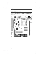

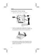


Install the Processor
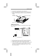
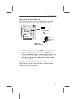
Connect the case switches and indicator LEDs to the bank of
switch and LED connectors J7. See the illustration below for a
guide to the pin functions of the J7 case connector.
17
21 22
Power LED
Pins 2-4-6
Speaker
Pins 1-3-5-7
Keylock
Pins 8-10
HDD LED Pins 15-16
1 2
Reset Switch Pins 17-18
Power Switch Pins 21-22


