PCB 1402-12ADB Скачать руководство пользователя страница 9


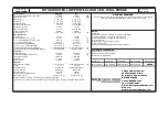
PCB Load & Torque, Inc.   

 Toll-Free in USA 866-684-7107   

 716-684-0001   

 www.pcbloadtorque.com


DUAL BRIDGE LOAD CELL OPERATION MANUAL 


2


1.0 INTRODUCTION 

 
Dual  bridge  fatigue-rated  load  cells  manufactured  by  PCB 
Load and Torque, Inc. are guaranteed to last 100 million fully 
reversed cycles (full tension through full compression). These 
load  cells  feature  high  accuracy  with  resistance  to  off-center 
loading, extraneous bending and side-loading forces. The load 
cells are manufactured using premium fatigue resistant steel or 
aluminum,  and  are  carefully  processed  to  ensure  mechanical 
and electrical integrity, as well as accuracy.  The nominal full 
scale output of the fatigue rated load cells is 2.0 mV/V. 
 
The  following  document  explains  how  to  properly  install  the 
dual  bridge  load  cell,  including  detailed  procedures  on 
specified  torques  installation,  adapter  thread  class  3  and 
tension pre-load specifications. 


2.0 SAFETY PRECAUTIONS 

 
Fatigue  rated  load  cells  are  designed  with  very  high  safety 
factors for overload, and of course, cyclic fatigue loads  when 
used  in  testing  programs.    However,  failure  of  the  load  cell 
structure  or  fasteners  used  in  the  load  cell  installation  may 
cause personal injury and equipment damage. 
 
It  is  important  to  provide  adequate  clearances  and  safety 
guards  or  shields  properly  surrounding  test  fixtures  where 
fatigue rated load cells are used.   
 
It is important to review the manufactured data when selecting 
rod ends and fasteners for load cell installation. Failure might 
occur due to combine measurement axis and extraneous loads 
if installation specifications are not followed.  All test fixtures 
designed  for  use  with  fatigue  rated  load  cells  should  be 
carefully evaluated for potential failure modes of the fixtures. 
 
It  is  important  to  use  threaded  fasteners  properly  when 
assembling test fixtures used with the load cells.  Fixtures with 
inadequately  designed  bolted  joints,  or  improperly  tightened 
threaded  fasteners  can  fail  before  the  parts  under  test  have 
completed the planned fatigue test cycles. 


3.0 OVERVIEW 

 
Dual  bridge  fatigue-rated  load  cells  are  specifically  designed 
for  repetitive  testing.  Applications  include  material  testing, 
component life cycle testing,  and structural testing.  The load 
cells  contain  an  extra  bridge  to  be  used  either  as  a  back-up 
incase  the  primary  bridge  fails  during  a  test,  or  just  for 
confirmation  of  the  primary  bridge  readings.  As  an  added 
benefit,  these  load  cells  are  extremely  resistant  to  extraneous 
bending and side loading forces 
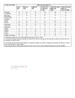
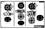
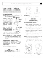


3.1 Dimensions 

The following figure and table give the general outline 
dimensions of the dual bridge fatigue-rated load cells. 


11 

12 


15 


10 

R

13 

14 

Model Series 

1403 

1404 

1408 

1411 

Capacity (Lbf) 

5k 

12.5k, 25k 

50k 

100k 

Dimensions 

(see Figure 1) 

(in) 

(mm) 

(in) 

(mm) 

(in) 

(mm) 

(in) 

(mm) 

2.50 

63.5 

3.50 

88.9 

4.50 

114.3 

6.50 

165.1 

1.37 

34.8 

1.75 

44.5 

2.50 

63.5 

3.50 

88.9 

1.13 

28.7 

1.75 

44.5 

2.00 

50.8 

3.00 

76.2 

1.25 

31.8 

1.63 

41.4 

2.25 

57.2 

3.25 

82.6 

4.12 

104.6 

6.06 

153.9 

8.00 

203.2 

11.00 

279.4 

R

2.54 

64.6 

3.53 

89.7 

4.85* 

123.2* 

6.10* 

154.9* 

3.50 

88.9 

5.13 

130.2 

6.50 

165.1 

9.00 

228.6 

8


1.25 

31.8 

2.42 

61.4 

3.50 

88.9 

5.38 

136.5 

9


1.25 

31.8 

2.25 

57.2 

3.50 

88.9 

4.50 

114.3 

10 

45º 

30º 

22.5º 

22.5º 

11 

0.25 

6.4 

0.37 

9.4 

0.48 

12.2 

0.75 

19.1 

12 

0.03 

0.76 

0.03 

0.76 

0.03 

0.76 

0.03 

0.76 

13 

1/4-28x1 3/4 

screw 12 pt. 

Qty. 8 

3/8-24x2 1/4 

screw 12 pt. 

Qty. 12 

1/2-20x3 1/2 

screw 12 pt. 

Qty. 16 

3/4-16x4 1/2 

screw 12 pt. 

Qty. 16 

14 

5/8-18 

1 1/4-12 

1 3/4-12 

2 3/4-8 

Thread Depth 

0.88 

22.4 

1.37 

34.8 

2.12 

53.8 

2.56 

65.0 

15 

5/8-18 

1 1/4-12 

1 3/4-12 

2 3/4-8 

Thread Depth 

0.88 

22.4 

1.37 

34.8 

1.71 

43.4 

3.15 

80.0 

*Indicates dimension with connector protector. 

Figure 1


- Dimensions 

Table 2


– Dimension Values 

Dim. 

Description 

Total Height 

Load Cell Height 

Tension Base Height 

Load Cell Body 

Height 

Load Cell Diameter 

R

Max. Clearance 

Radius 

Bolt Circle Diameter 

Top Loading Surface 

Diameter 

Bottom Loading 

Surface Diameter 

10 

Angle Between 

Screws 

11 

Screw Head Height 

12 

Bottom Loading 

Surface Height 

13 

Screw for Tension 

Base 

14 

Load Cell Mounting 

Thread 

15 

Tension Base 

Mounting Thread 


Table 1


– Dimension 

Descriptions 

Содержание 1402-12ADB

Страница 1: ... LOAD CELL DUAL BRIDGE Installation and Operating Manual For assistance with the operation of this product contact PCB Piezotronics Inc Toll free 800 828 8840 24 hour SensorLine 716 684 0001 Fax 716 684 0987 E mail info pcb com Web www pcb com ...

Страница 2: ... repair User servicing or repair is not recommended and if attempted may void the factory warranty Calibration Routine calibration of sensors and associated instrumentation is recommended as this helps build confidence in measurement accuracy and acquired data Equipment calibration cycles are typically established by the users own quality regimen When in doubt about a calibration cycle a good rule...

Страница 3: ...ory customer service representative Warranty All equipment and repair services provided by PCB Piezotronics Inc are covered by a limited warranty against defective material and workmanship for a period of one year from date of original purchase Contact PCB for a complete statement of our warranty Expendable items such as batteries and mounting hardware are not covered by warranty Mechanical damage...

Страница 4: ... O PCB板 X O O O O O 电气连接器 O O O O O O 压电晶体 X O O O O O 环氧 O O O O O O 铁氟龙 O O O O O O 电子 O O O O O O 厚膜基板 O O X O O O 电线 O O O O O O 电缆 X O O O O O 塑料 O O O O O O 焊接 X O O O O O 铜合金 黄铜 X O O O O O 本表格依据 SJ T 11364 的规定编制 O 表示该有害物质在该部件所有均质材料中的含量均在 GB T 26572 规定的限量要求以下 X 表示该有害物质至少在该部件的某一均质材料中的含量超出 GB T 26572 规定的限量要求 铅是欧洲RoHS指令2011 65 EU附件三和附件四目前由于允许的豁免 CHINA RoHS COMPLIANCE ...

Страница 5: ...te O O X O O O Wires O O O O O O Cables X O O O O O Plastic O O O O O O Solder X O O O O O Copper Alloy Brass X O O O O O This table is prepared in accordance with the provisions of SJ T 11364 O Indicates that said hazardous substance contained in all of the homogeneous materials for this part is below the limit requirement of GB T 26572 X Indicates that said hazardous substance contained in at le...

Страница 6: ... 06 in x 3 50 in 153 90 mm x 88 90 mm 8 Weight 21 lb 4 53 kg Mounting Thread 1 14 UNS 3B No Metric Equivalent Sensing Element Strain Gage Strain Gage Mounting Torque 1400 in lb 158 Nm Deflection at Full Scale Capacity 0 001 in 0 03 mm Electrical Connector PT02E 10 6P 2 PT02E 10 6P 2 All specifications are at room temperature unless otherwise specified In the interest of constant product improvemen...

Страница 7: ...10 3 12X THRU n5 125 130 2 B C 1 14UNS 3B x1 37 34 8 45 90 n2 59 65 8 1 75 44 5 n6 06 153 9 81 20 6 1 63 41 4 CONNECTOR A PTO2A 10 6P CONNECTOR WIRING CODE TYPICAL PIN A EXC PIN B SIG PIN C SIG PIN D EXC PIN E N C PIN F N C CONNECTOR B DUAL BRIDGE ONLY 1202 1402 SERIES LOAD CELLS 1 SUPPLIED WITH MATING FASTENERS 1202 1402 SERIES BASES n2 59 65 8 n5 125 130 2 B C 3 8 24 UNF 2B x 88 12X 1 45 n6 06 1...

Страница 8: ...ELECTRICAL INSTALLATION 5 5 1 Electrical Drawing Western Regional Std 5 5 2 Cable Grounding Considerations 5 6 0 CALIBRATION 5 6 1 Calibration Certificate Description 5 6 1 1 Measured Output 6 6 1 2 Hysteresis 6 6 1 3 Best Fit Output 6 6 1 4 Strain Gage Measurements 6 6 1 5 Shunt Calibration Standard Resistor 6 6 1 6 Static Error Band SEB 6 7 0 MOMENT COMPENSATION 6 8 0 FATIGUE OVERLOAD 6 9 0 SHUN...

Страница 9: ...the parts under test have completed the planned fatigue test cycles 3 0 OVERVIEW Dual bridge fatigue rated load cells are specifically designed for repetitive testing Applications include material testing component life cycle testing and structural testing The load cells contain an extra bridge to be used either as a back up incase the primary bridge fails during a test or just for confirmation of...

Страница 10: ...note that the performance of the load cell may be affected if the factory installed mounting base is removed or modified 4 2 Mounting Load Cell to a Standard Base or Custom Fixture If the load cell is to be mounted to a custom base or fixture it is necessary to consider the following 1 The thickness of the new base or fixture must not be any thinner than the original base supplied with the load ce...

Страница 11: ...ector Protector 1 Remove the 4 40 x 1 4 button head cap screws from the connector using a 1 16 hex wrench as shown in Figure 7 2 Carefully pull the connector from the load cell Take care to not break or loosen any wire connections 3 Slide the connector protector 54823 02 behind the connector as shown in Figure 8 4 Apply a drop Loctite Threadlocker Blue 242 to the threads of the 4 40 x 3 8 socket h...

Страница 12: ...m wiring may result in unstable or noisy signals A simple test with a voltmeter connected between the power cord ground and the structure on which the load cell is mounted can confirm that the structure has been properly grounded If the power cord ground and structure ground are not at the same potential it may be necessary to provide a secure structure ground perhaps by driving a copper rod and a...

Страница 13: ...ls are adjusted such that the error due to eccentric loading is less than 0 1 per inch of offset Side loads moments and torque must be limited to avoid electrical or mechanical damage to the load cell The allowable extraneous loads are directly related to the rated capacity of the load cell Maximum side force allowed is 100 of the rated capacity for the load cell Maximum moment allowed is 100 of t...

Страница 14: ...ation certificate and adjust the span or gain until the display reads the force value stated on the certificate 4 Repeat steps 1 3 to verify that a valid calibration setting has been obtained 5 If possible apply a known load to the measurement system to further verify that the calibration has been accurately set up 9 3 Estimating Shunt Resistor for a Given Load The following formula can be used to...

Страница 15: ...bridge resistances A D excitation and B C the signal leads 9 Check bridge balance 10 Keep a record of your observations correct problems or contact PCB factory for assistance 11 2 1 Estimating Bridge Balance using an Ohm Meter A load cell that has been severely overloaded will exhibit a significant zero offset in the Wheatstone bridge It can be useful to estimate the bridge unbalance using a digit...

Страница 16: ...e factory for any reason For calibration services if possible a copy of the purchase order covering the requested services should be included with the returned load cell 13 0 WARRANTY Standard warranty on dual bridge load cells covers parts and workmanship For full details refer to the Warranty Statement supplied with each load cell If the load cell is defective for reasons other than overloads re...

Отзывы: