PCB Piezotronics 683A110203 Скачать руководство пользователя страница 16


PAGE 11 


SENSO

RS AN

D INS

TRUME

N

TATI

O

N F

O

R MAC

HINE 

CON

DITI

ON M

ON

IT

ORIN

G


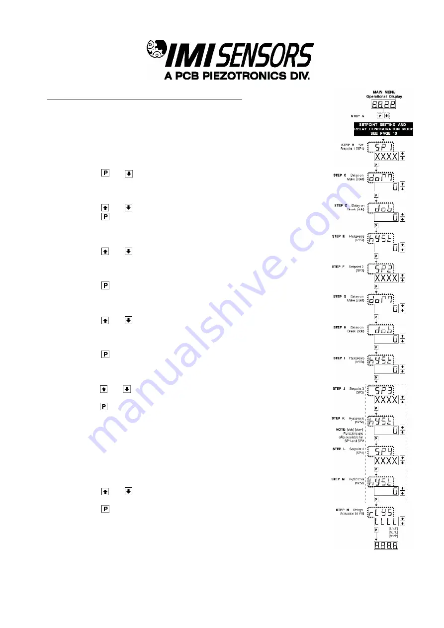
Setpoint Setting and Relay Configuration Mode 


The following programming steps are required to enter the setpoint values and 
configure the relay functions in a meter with four relays using four setpoints. Generally 
if less than four relays are installed the software auto detects the missing relays and 
deletes reference to them from the menu. In some cases setpoints without relays are 
operational for display purposes only. 


STEP A Enter the Setpoint Mode 

1) 

Press the 

 and 

 buttons at the same time. 

Display toggles between [SP1] and the previous [SP1] setting. 


STEP B Setpoint1 (SP1) 

1) 

Using the 

 and 

 buttons, adjust the display to the desired SP1 value. 

2) 

Press the 

 button. Display toggles between [doM] and the previous [doM] 

setting.


STEP C  Set the SP1 Delay-on-Make (doM) Delay Time Setting 

1)  Using the 

 and 

 buttons, adjust the display to the desired [doM] value 

(0 to 9999 seconds). The reading must continuously remain in an alarm 
condition until this delay time has elapsed before the relay will make contact 
(energize). 

2)  Press the 

 button. Display toggles between [dob] and the previous [dob]  

setting. 

 
STEP D Set the SP1 Delay-on-Break (dob) Delay Time Setting 

1) 

Using the 

 and 

 buttons, adjust the display to the desired [dob] value (0-

9999 seconds). The reading must continuously remain in a non-alarm condition 
until this delay time has elapsed before the relay will break contact (de-
energize). 

2) 

Press the 

 button. Display toggles between [hYST] and the previous [hYST] 

setting

 
STEP C Set the Hysteresis Setting for Setpoint 1 

1) 

Using the 

 and 

 buttons, adjust the display to the desired hysteresis [hYST] 

value. 

2) 

Press the 

 button. Display toggles between [SP2] and the previous [SP2] 

setting.


Note: Steps, F, G, H, and J have functionally the same procedure as steps B, C, D, 
and E shown above. 
 
STEP F Set Setpoint 2 (SP2) 
STEP G Set the SP2 Delay-on-Make (doM) Delay Time Setting 
STEP H Set the SP2 Delay-on-Break (dob) Delay Time Setting 
 
STEP I Set the Hysteresis Setting for Setpoint 2 

1) 

Using the 

 and 

 buttons, adjust the display to the desired hysteresis [hYST] 

       value. 

2) 

Press the 

 button. Display toggles between [SP3] and the previous [SP3]  

       setting. 


SETPOINT 3, 4, AND RELAY ACTIVATION MODE CONTINUED NEXT PAGE. 

Содержание 683A110203

Страница 1: ...CP sensors Installation and Operating Manual For assistance with the operation of this product contact PCB Piezotronics Inc Toll free 800 959 4464 24 hour SensorLine 716 684 0001 Fax 716 684 3823 E ma...

Страница 2: ...ty regimen When in doubt about a calibration cycle a good rule of thumb is to recalibrate on an annual basis It is also good practice to recalibrate after exposure to any severe temperature extreme sh...

Страница 3: ...rchase Order should include authorization to proceed and return at current pricing which can be obtained from a factory customer service representative Contact Information International customers shou...

Страница 4: ...isclosure Table Pb Hg Cd Cr VI PBB PBDE O O O O O O PCB X O O O O O O O O O O O X O O O O O O O O O O O O O O O O O O O O O O O O O X O O O O O O O O O X O O O O O O O O O O O X O O O O O X O O O O O...

Страница 5: ...e O O X O O O Wires O O O O O O Cables X O O O O O Plastic O O O O O O Solder X O O O O O Copper Alloy Brass X O O O O O This table is prepared in accordance with the provisions of SJ T 11364 O Indica...

Страница 6: ...Model 683A1 ICP Process Indicator Controller Operating Guide with Enclosed Warranty Information 3425 Walden Avenue Depew New York 14043 2495 Phone 716 684 0003 Fax 716 684 3823 Toll Free Line 1 800 95...

Страница 7: ...Page 4 Controls and Indicators Page 5 Glossary of Programming Symbols Page 6 Software Logic Tree Page 7 Programming the 683A1 Page 8 Wiring and Installation Page 13 Configuring the 683A1 Page 17 Acce...

Страница 8: ...one count to the full scale range of 1999 to 9999 12000 counts 24Vdc 4mA excitation to power sensor Standard Internal DIP switch selectable vibration ranges include Acceleration g s Velocity in sec D...

Страница 9: ...lays negative Decimal Selection Front panel button selectable X X X X Positive Overrange Top segments of digital display flash Negative Overrange Bottom segment of digital display flash Relay Output T...

Страница 10: ...etting mode Up Button When in the operational display pressing the button alone allows you to view and reset the Peak and Valley Highest and Lowest Readings When in calibration mode or the setpoint se...

Страница 11: ...can be increased by pressing and releasing the button or decreased by pressing and releasing the button When two buttons are shown side by side and enclosed by a dotted line they must be pressed at t...

Страница 12: ...is an intelligent meter with a hierarchical software structure designed for easy programming and operation as shown below in the software logic tree After the meter has been powered up the four digits...

Страница 13: ...ggles between cAL and out STEP B Select Between Calibration of Input or Output Note If the analog output option is not present Step B is skipped and the program goes directly from Step A to Step C 1 P...

Страница 14: ...onnect a multimeter to pins 16 and 17 on the output module See Rear Panel Pinouts on Page 8 Using the and buttons adjust the analog output to the desired low value as shown on the multimeter display c...

Страница 15: ...toggles between Anhi and the previous Anhi setting STEP G Setting the Digital Span Point for Analog High Output 1 Using the and buttons adjust the display to the desired digital value which sets the p...

Страница 16: ...y time has elapsed before the relay will make contact energize 2 Press the button Display toggles between dob and the previous dob setting STEP D Set the SP1 Delay on Break dob Delay Time Setting 1 Us...

Страница 17: ...value 2 Press the button Display toggles between hYST and 0 STEP M Set the Hysteresis Setting for Setpoint 4 1 Using the and buttons adjust the display to the desired hysteresis hYST value 2 Press th...

Страница 18: ...l connectors for all input and output connections The power supply connections pins 14 and 15 have a unique plug and socket outline to prevent cross connection The main board and input signal conditio...

Страница 19: ...ion To Maintain Conformance I O Shields must be connected to Pin 3 on the Panel Meter and all Supplied Accessories must be wired as shown Power Supply Option 2 1 2 3 4 5 8 9 10 11 14 15 ICP SENSOR SIM...

Страница 20: ...vate the LOCK or DIM functions from the rear of the meter the respective pins have to be connected to the COMMON pin This pin is connected to the internal power supply ground Pin 20 HOLD By connecting...

Страница 21: ...PAGE 16 SENSORS AND INSTRUMENTATION FOR MACHINE CONDITION MONITORING Case Dimensions and Panel Cutout...

Страница 22: ...removing the back cover and sliding the ICP Interface PC Board out of the Panel Meter Controller Once removed the DIP switch should be configured per one of the conditions in the following table Range...

Страница 23: ...forms a seal between the base and the panel The cam hinge prevents the cover from closing when opened until pushed closed The cover has a tapered recess that when closed forms a capillary seal with a...

Страница 24: ...olycarbonate case and is held firmly in place by spring type non return clips Once the metal case has been fitted to the polycarbonate case it cannot be removed With the metal case in place the meter...

Страница 25: ...ischarge ESD can damage electrical devices Similar to a capacitor a cable can hold a charge caused by triboelectric transfer such as that which occurs in the following Laying on and moving across a ru...

Страница 26: ...mp Form A Relays SPST Frequency Response 0 3Hz to 10kHz Standard 1 3Hz to 1kHz 2 10Hz to 10kHz 3 10Hz to 1kHz Accessories 0 None 1 96x48mm Clear Lockable Front Cover NEMA 4X Splash Proof 2 Metal Surro...

Страница 27: ...ior to servicing at no charge Before returning the unit please consult a factory IMI applications engineer concerning the situation as certain problems can often be corrected with simple on site proce...

Страница 28: ...price refunded IMI offers to all customers at no charge 24 hour phone support This service makes product or application support available to our customers day or night seven days a week When unforese...

Страница 29: ...5VAC 95 370VDC 85 265VAC 95 370VDC Current Consumption Typical 2 5W 2 5W Current Consumption Max 3 5W 3 5W Excitation Voltage 1VDC 24VDC 24VDC Constant Current Excitation 1mA 4mA 4mA Physical Size Dep...

Страница 30: ......

Отзывы: