


REACTION TORQUE SENSOR OPERATION MANUAL
2
1.0 INTRODUCTION
Reaction torque sensors manufactured by the Force-
Torque Division of PCB are strain gage based
measuring instruments suitable for a wide range of
torque measurement applications. They are rigid
structures with no moving parts and are typically
mounted in a fixed position. Their output signal
varies proportionally to an applied torsional force.
Capacities range from 5 to 500k in-lb (0.56 to 56.5k
N-m).
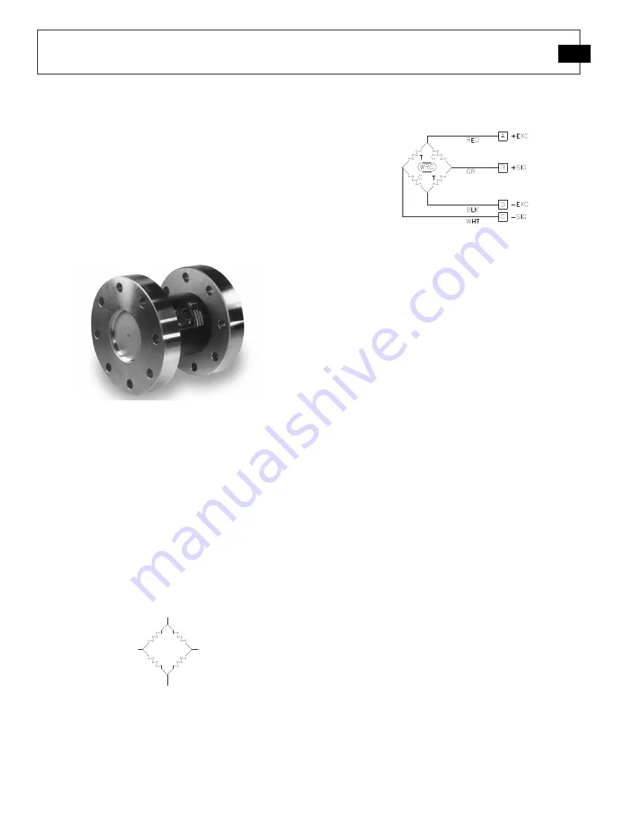
Figure 1
–
Flange Mount Reaction Torque Sensor
Due to the fact that these sensors do not utilize
bearings, slip rings, or any other rotating elements,
their installation and use can be very cost effective.
Reaction torque sensors are particularly useful in
applications where the introduction of a rotating
mass between the driver and driven is undesirable.
All models utilize strain gages configured into a
Wheatstone Bridge Circuit to produce the primary
sensing element. The four-arm Wheatstone Bridge
configuration is shown below in
Figure 2
.
Figure 2 - Wheatstone Bridge Circuit
Most PCB reaction torque sensors follow a wiring
code established by the Western Regional Strain
Gage Committee as revised in May 1960. The
wiring code is as follows:
Figure 3 - Western Regional Strain Gage Committee
Wiring Code
Refer to the wiring drawing included with this
manual for specific wiring of the supplied torque
sensor.
The gages are bonded to the sensor
’
s structure.
Typically, a regulated DC or AC excitation is
applied between A and D of the bridge. When
torque is applied to the sensor, the Wheatstone
Bridge becomes unbalanced, causing an output
voltage between B and C which is proportional to
the applied torque. The magnitude of the output
voltage corresponds to the torsional deflection of
the sensor structure and therefore the applied torque.
This configuration allows for temperature and
pressure compensation, as well as cancellation of
signals caused by forces not directly applied to the
axis of the applied load. Output is typically
expressed in units of millivolt per volt of excitation.
Optional signal conditioners are available from
PCB. A signal conditioner may have analog voltage
output, current output, or digital output. Digital
display signal conditioners are also available.
Axis Definition
PCB force products comply with the Axis and
Sense Definitions of NAS-938 (National Aerospace
Standard-Machine Axis and Motion) nomenclature
and recommendations of the Western Regional
Strain Gage committee. These axes are defined in
terms of a "Right Handed" orthogonal coordinate
system as show below. A (+) sign indicates force in
a direction which produces a (+) signal voltage and
generally defines a clockwise torque.
VOLTAGE IN
SIGNAL OUT
SIGNAL IN
VOLTAGE OUT