21
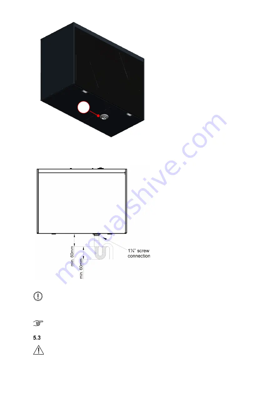
Fig. 21: Sink valve screw connection on unit version LEFT
A siphon must be attached to the screw connection so that the upper edge of the surge tank is at least 60 mm below
the screw connection and the minimum liquid level is 60 mm.
Fig.
22: Condensate drain (version LEFT)
The siphon must not be connected directly to the sewer tunnel network (e.g. whereby the condensate
flows freely into a funnel with a siphon connected to the sewer line)
Siphons can dry out! The siphon must always be topped up with water when:
•
The unit is commissioned
•
The siphon starts making (slurping/gurgling) noises
We generally recommend using a dry siphon!
(No functional restrictions if it dries out, no need for a
2nd siphon)
Electrical connections
Electrical connections are to be implemented in accordance with the standards
specific to the relevant country and by qualified personnel only!
The FOCUS unit must be electrically connected to the mains power supply via the mains unit lead with a CEE 7/4
plug. This is to be plugged into a 230 VAC CEE 7/4 socket. The control panel is connected to the ventilation unit with
a 4-wire cable using the flat connector
C
. The cable for an optional connected pre-heater is connected directly to the
A
Содержание FOCUS 200 Base
Страница 1: ...Translation of the original instruction manual Heat Recovery Unit FOCUS 200 Base...
Страница 30: ...30 Dimensions Fig 33 Dimensional drawing...
Страница 31: ...31 FOCUS 200 Base terminal scheme Fig 34 Terminal assignment terminal plan...
Страница 36: ...36 PDE Manual_Focus 200 Base_V1 1 V1122 DE Subject to change...


