4
Visuality™ Model T7714 Quick Start Guide
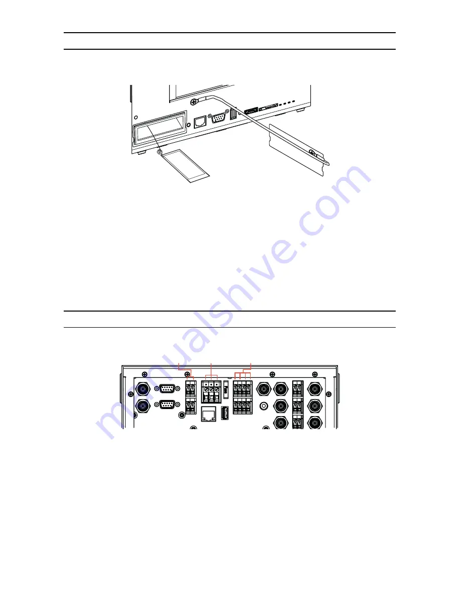
2.0 Connect the cellular modem
The T7714 provides a slot for a cellular modem card. To install a cellular modem in the T7714:
Figure 2.
Installing the cellular modem card on the T7714
1.
Use a screwdriver to remove the
Modem
cover on the front of the T7714 unit.
2.
Plug the cellular modem card into the antenna cable inside of the unit.
3.
Slide the modem card into the tray inside the T7714 until the card clicks into place.
4.
Use a screwdriver to reattach the
Modem
cover to the front of the T7714 unit.
To remove the cellular modem card, use a screwdriver to remove the Modem cover on the front of the T7714
unit. Gently press on the modem card. The card will eject from the card slot.
3.0 Connect power
Figure 3.
T7714 power connectors
To connect the main power:
1.
Connect the wires for the power connector into the terminal block labeled ACC GND +12V.
2.
Connect the wire for the vehicle accessory port into the ACC block.
3.
Connect the wires for the vehicle battery into the GND and +12V blocks.
4.
The unit will turn on when you connect the ACC wire to the vehicle accessory line. You may verify that the
Power LED on the front panel of the T7714 is lit.
Modem
Head
phone
Ethernet
Console
USB
Reset
eSATA
SIM C
ard
Power
COM
Video
Network
Cellular Modem
Card
VIDEO OUT
AUDIO OUT
OBD II
PTZ
AUX PWR
AUX GND
ETHERNET
ACC GND +12V
Fuse
USB
INPUT PWR
INPUT GND
1 2 3 4
MIC
AUDIO IN
1
2
3
1
2
3
VIDEO IN
Auxiliary
Inputs 1-4
(Terminal Block)
Main Power
(Terminal Block)
Auxiliary
Power Output
(Terminal Block)


