background image

Connecting the 10/100Base-T Ethernet Interfaces

26

CopperLink Model CL1300MDE User Manual 

2


• Installation

Connecting the 10/100Base-T Ethernet Interfaces

The Long Range Ethernet Extender has four unshielded RJ-45 auto-MDIX10/‘100Base-T interfaces. These 
are designed to connect directly to a 10/100Base-TX network.

Connecting Power

If you will be using an AC power supply to provide power to the CL1300MDE, go to section 

“External AC 

universal power supply”

. Otherwise, go to section 

“DC power supply”

 on page 27.

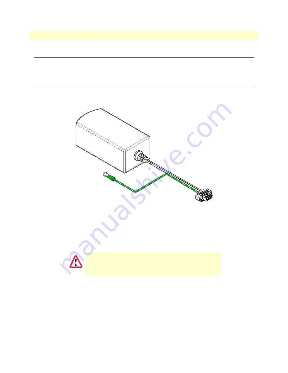
Figure 11. AC power supply

External AC universal power supply

To connect the AC power supply, do the following:

1.

Attach the ground wire’s #10 ring terminal to a wall outlet which has earth ground (if a suitable outlet is 
not available use a grounding electrode such as a ground rod, water pipe, building steel, etc.). 

2.

Connect the terminal block connector to the terminal block base on the CL1300MDE.

3.

Use a flat-tip screwdriver to tighten the two screws securing the connector to the base.

The CL1300MDE is ready to be powered up. Refer to chapter 3,

 “Operation” 

on page 29.

Do not over-tighten the ground connection.

CAUTION

Содержание 03343D1-002

Страница 1: ... support patton com WWW www patton com Part Number 07MCL1300MDE Rev A Revised November 14 2018 Important This is a Class A device and is intended for use in a light industrial environment It is not intended nor approved for use in an industrial or residential environment REGULATORY MODEL NUMBER 03343D1 002 Start Installation For Quick ...

Страница 2: ...e product should it fail within one year from the first date of shipment This warranty is limited to defects in workmanship or materials and does not cover customer damage abuse or unauthorized modification If this product fails or does not perform as warranted your sole recourse shall be repair or replacement as described above Under no condition shall Patton Electronics be liable for any damages...

Страница 3: ... 4 Configuration 32 5 Wizard Interface 35 6 CLI Operation and Configuration 40 7 Contacting Patton for assistance 44 A Compliance information 47 B Specifications 49 C Factory replacement parts and accessories 52 D Interface pinouts 54 E Installing 552 GS2 High Speed Surge Protectors 56 ...

Страница 4: ...r 16 External AC universal power supply 16 External 48 VDC power supply 17 2 Installation 18 Introduction 19 Configuring DIP Switch S2 19 Hardware DIP switch configuration 21 Installing the device 21 DIN rail installation 22 Connecting the CopperLink Line Interfaces 23 Connecting the 10 100Base T Ethernet Interfaces 26 Connecting Power 26 External AC universal power supply 26 DC power supply 27 3 ...

Страница 5: ...ntroduction 45 Contact information 45 Contacting Patton Technical Services for Free Support 45 Warranty Service and Returned Merchandise Authorizations RMAs 45 Warranty coverage 45 Out of warranty service 46 Returns for credit 46 Return for credit policy 46 RMA numbers 46 Shipping instructions 46 A Compliance information 47 Compliance 48 EMC 48 Safety 48 Radio and TV Interference FCC Part 15 48 EC...

Страница 6: ...nsions 51 Weight 51 Compliance 51 C Factory replacement parts and accessories 52 Factory replacement parts and accessories 53 D Interface pinouts 54 CopperLink line ports C1 and C2 55 2 wire CL1314MDE 55 4 wire CL1324MDE 55 Ethernet ports 0 to 3 55 E Installing 552 GS2 High Speed Surge Protectors 56 Introduction 57 Installing the 552 GS2 surge protectors 57 ...

Страница 7: ...he device onto the DIN rail 23 8 CL1300MDE ports 24 9 CL1300MDE RJ 45 twisted pair line interfaces 24 10 CL1300MDE Topologies 25 11 AC power supply 26 12 Terminal block and ground wiring labels 27 13 CL1300MDE front panel LEDs 30 14 Login 36 15 Web Wizard Home page 37 16 Choose Wizard 37 17 Basic Setup 37 18 Configure Preview Option 39 19 Confirmation 39 20 Connect IT Model 552 GS2 57 21 How to co...

Страница 8: ...8 List of Tables 1 General conventions 12 2 TCPAM Rates 21 3 CL1300MDE front panel LEDs 31 4 RJ45 socket 10 100Base T 55 ...

Страница 9: ...pter 5 on page 35 describes how use the browser interface that allows you to configure and manage the Ethernet extender Chapter 6 on page 40 describes how to connect a PC to configure the CopperLink CL1300MDE using the CLI Chapter 7 on page 44 contains information on contacting Patton technical support for assistance Appendix A on page 47 contains compliance information for the CL1300MDE Appendix ...

Страница 10: ...idelights The shock hazard symbol and WARNING heading indicate a potential electric shock hazard Strictly follow the warn ing instructions to avoid injury caused by electric shock The alert symbol and WARNING heading indicate a poten tial safety hazard Strictly follow the warning instructions to avoid personal injury The shock hazard symbol and CAUTION heading indicate a potential electric shock h...

Страница 11: ...l Safety Protective Ground the wall outlet or socket must have an earth ground For DC powered devices ensure that the interconnecting cables are rated for proper voltage current anticipated temperature flammability and mechanical serviceability WAN LAN PSTN ports connections may have hazard ous voltages present regardless of whether the device is powered ON or OFF PSTN relates to interfaces such a...

Страница 12: ...lt in complete or inter mittent failures Do the following to prevent ESD Always follow ESD prevention procedures when removing and replacing cards Wear an ESD preventive wrist strap ensuring that it makes good skin contact Connect the clip to an unpainted surface of the chassis frame to safely channel unwanted ESD voltages to ground To properly guard against ESD damage and shocks the wrist strap a...

Страница 13: ... keys such as SHIFT CTRL C and so on Elements in square brackets are optional a b c Alternative but required keywords are grouped in braces and are separated by vertical bars blue screen Information you enter is in blue screen font screen Terminal sessions and information the system displays are in screen font An hash sign at the beginning of a line indicates a comment line Table 1 General convent...

Страница 14: ...14 Chapter 1 General information Chapter contents CopperLink Model CL1300MDE overview 15 Features 15 Power input connector 16 External AC universal power supply 16 External 48 VDC power supply 17 ...

Страница 15: ...ns train stations digital sensors or IP cameras Patton Ethernet Extenders offer the industry s optimum combination of speed and distance Patton s CopperLink Ethernet Extenders ensure hassle free set up and oper ation while achieving the highest possible line rate for the required distance and electromagnetic environment Users can hard set the desired line rate via DIP switch GUI or console Telnet ...

Страница 16: ...d to a DC power supply that is not included See section Power on page 51 The power connection to the CL1300MDE is a terminal block see figure 2 Rated voltage 5 VDC Rated current 1 A Figure 2 Terminal block power connection External AC universal power supply For additional specifications see section Power on page 51 Output from power supply 5 VDC 2 A Input to power supply universal input 100 240 VA...

Страница 17: ...locking connector 3 5 mm pitch Transient over voltage protection 100VDC at 2 ms Output Rated voltage 5 VDC 5 5W Rated current 1 A DC The external DC adapter shall be a listed limited power source that incorporates a disconnect device and shall be positioned within easy reach of the operator The interconnecting cables shall be rated for the proper voltage current anticipated tem perature flammabili...

Страница 18: ...P Switch S2 19 Hardware DIP switch configuration 21 Installing the device 21 DIN rail installation 22 Connecting the CopperLink Line Interfaces 23 Connecting the 10 100Base T Ethernet Interfaces 26 Connecting Power 26 External AC universal power supply 26 DC power supply 27 ...

Страница 19: ...onnecting Power on page 26 Configuring DIP Switch S2 The DIP switches are located inside the device They enable you to configure the TCPAM Rate preset These settings are applied when the device powers on and they cannot be changed while the device is powered on Keep this in mind if you plan on adjusting these settings later remotely as the DIP switch settings at boot will always take priority 1 Us...

Страница 20: ...Switch S2 20 CopperLink Model CL1300MDE User Manual 2 Installation Figure 3 Removing DIP switch cover 2 figure 4 shows the orientation of the DIP switches in the On and Off positions Figure 4 DIP switch S2 orientation ...

Страница 21: ...ce If you are installing the unit on a DIN rail see section DIN rail installation Otherwise place the unit on a desktop or similar sturdy surface that offers easy access to the cables The unit should be installed in a dry envi ronment with sufficient space to allow air circulation for cooling Note For proper ventilation leave at least 2 inches 5 cm on all sides of the device Table 2 TCPAM Rates Sw...

Страница 22: ...t see figure 5 can be attached to top hat NS 35 7 5 35 H 7 5 D mm and NS 35 15 35 H 15 D mm section types of DIN rail see figure 6 Figure 5 DIN rail mounting clip location Figure 6 DIN rail types 2 Install the device onto the DIN rail by inserting the upper DIN rail lip into the upper DIN rail clip slot see callout 1 on figure 7 on page 23 ...

Страница 23: ...e connected using a twisted pair unconditioned dry metal wire between 19 0 9mm and 26 AWG 0 4mm Leased circuits that run through signal equalization equip ment are not acceptable The Ethernet Extender is equipped with RJ 45 interface ports C1 and C2 see figure 8 on page 24 that con form to the T568B standard As such any standard Category 5e cable can be used to directly connect two extenders The C...

Страница 24: ...0MDE extenders Keep the following in mind The RJ 45 CopperLink connector on the CL1314MDE s twisted pair interface is polarity insensitive and is wired for a 2 wire interface The RJ 45 CopperLink connector on the CL1324MDE s twisted pair interface is polarity insensitive and is wired for a 4 wire interface Port C1 connects to port C2 CL1300MDE or the Line port CL1300 R or CL1300R R Port C2 connect...

Страница 25: ...Connecting the CopperLink Line Interfaces 25 CopperLink Model CL1300MDE User Manual 2 Installation Figure 10 CL1300MDE Topologies ...

Страница 26: ...rwise go to section DC power supply on page 27 Figure 11 AC power supply External AC universal power supply To connect the AC power supply do the following 1 Attach the ground wire s 10 ring terminal to a wall outlet which has earth ground if a suitable outlet is not available use a grounding electrode such as a ground rod water pipe building steel etc 2 Connect the terminal block connector to the...

Страница 27: ...imum stranded ground wire remove 1 4 inch of insulation from the ground wire and insert it into the ground terminal on the CL1300MDE terminal block see figure 12 3 Use a small flat tip screwdriver to secure the wire into the terminal block 4 Attach the ground wire s 10 ring terminal to a wall outlet which has earth ground if a suitable outlet is not available use a grounding electrode such as a gr...

Страница 28: ...the wire into the terminal block 8 Route a wire from the negative output of the DC source to the terminal on the CL1300MDE termi nal block see figure 12 on page 27 9 Use a small flat tip screwdriver to secure the wire into the terminal block The CL1300MDE is ready to be powered up Refer to chapter 3 Operation on page 29 ...

Страница 29: ...29 Chapter 3 Operation Chapter contents Applying power 30 Status LEDs 30 ...

Страница 30: ... has the ground wire connected to it DC power source Power up the DC power source The CL1300MDE activates when power is applied from an AC or DC source Go to section Status LEDs Status LEDs Front panel LEDs indicate the status of power CopperLink and Ethernet connections see figure 13 and table 1 on page 5 The following sections describe power up reading the LED status monitors and using the built...

Страница 31: ...t is in data mode Slow blink Port is in handshake mode looking for a remote signal Fast blink Port is in training mode active communication with remote Green LED Pair 0 wires OFF Port is configured as DOWN Port is configured as DOWN ON Port is in data mode Port is in data mode Slow blink Port is in handshake mode looking for a remote signal Port is in handshake mode looking for a remote signal Fas...

Страница 32: ...32 Chapter 4 Configuration Chapter contents Introduction 33 ...

Страница 33: ...l always override the other configuration access methods for some settings This will be problematic if you need to change these settings remotely The factory installed configuration is shown below Note There is a hard coded IP address 192 168 200 10 24 assigned to the CL1314MDE however DHCP client is also enabled to provide an IP address from your DHCP server if one can be found Both IP addresses ...

Страница 34: ...port line 0 0 service mode 4 wire mode remote bind switch group DEFAULT LINE_0_0 no shutdown port line 1 0 service mode 4 wire mode local bind switch group LINE_1_0 no shutdown Refer to the appropriate chapter to configure and manage the CL1300MDE To use the Wizard Interface on a web browser see Chapter 5 on page 35 To connect a PC to configure the CopperLink CL1300MDE using the CLI see Chapter 6 ...

Страница 35: ...35 Chapter 5 Wizard Interface Chapter contents Introduction 36 Connect with Web GUI 36 ...

Страница 36: ...ble with the CL1300MDE Note For detailed information about configuring and operating guidance set up procedures and troubleshooting refer to the CopperLink 1300 Series User Manual available online at www patton com manuals Connect with Web GUI 1 Connect via web browser to the default address 192 168 200 10 2 Log in with the default username admin without a password Once the network connection is e...

Страница 37: ...ed you will have the options of supported set ups as shown in Figure 16 Click on CL1300MDE Basic Setup Figure 16 Choose Wizard Clicking on the CL1300MDE Basic Setup will bring up the most common configurations used on the Copper Link Ethernet Extenders Figure 17 depicts options to configure through the Basic Setup wizard Figure 17 Basic Setup ...

Страница 38: ...cally used at the remote device or remote network Your CopperLink CL1300MDE is already configured with port C1 as Remote and C2 as Local Service Mode Configures the number of pairs wires you want to use The CL1300MDE will default to the maximum number of wires available on your version of the CopperLink CL1314MDE 2 wire or CL1324MDE 4 wire Annex Consult technical support before changing this setti...

Страница 39: ...review Option When the user chooses the save and reboot option a prompt will ask you to confirm If the configuration is cor rect select Yes as shown in figure 19 Figure 19 Confirmation Typically the time to reboot and reestablish a CopperLink connection so it can pass traffic will be less than 2 minutes ...

Страница 40: ...e IP address default 192 168 200 10 41 Change the default username 41 Save the Configuration 41 CopperLink Line Commands 41 CopperLink Ports 41 Local and Remote 42 Annex Type 42 Line Rate Configuration 42 Modulation Scheme 42 Signal to Noise Ratio 42 Description 42 Service Mode 42 Shutdown 43 Exit 43 Show 43 ...

Страница 41: ...de configure node cfg context ip router node ctx ip router interface LAN node if ip router LAN no ipaddress 192 168 200 10 24 node if ip router LAN ipaddress new address new mask Change the default username The default username will be removed once a new one is created Follow the command sequence below node enable node configure node cfg superuser username password password Save the Configuration ...

Страница 42: ...u choose to hard set this value Higher TC PAM rates are ideal for shorter cable runs offering max symmetrical upstream downstream speeds of 11 4 Mbps TCPAM64 and 15 3 Mbps TCPAM128 per pair node prt line 0 0 tcpam auto 16 32 auto 64 128 16 32 64 128 Signal to Noise Ratio Configures the acceptable noise margin for adaptive rate SNR is the relative strength of the DSL signal to Noise ratio 6dB is ge...

Страница 43: ...ion and Configuration Shutdown Disables or enables CopperLink port s node prt dsl 0 0 no shutdown Exit Goes back to parent mode node prt dsl 0 0 exit Show Displays all the configured options of the CL1300MDE CopperLink port s node cfg show port line 0 0 node cfg show port line 1 0 ...

Страница 44: ...ontact information 45 Contacting Patton Technical Services for Free Support 45 Warranty Service and Returned Merchandise Authorizations RMAs 45 Warranty coverage 45 Out of warranty service 46 Returns for credit 46 Return for credit policy 46 RMA numbers 46 Shipping instructions 46 ...

Страница 45: ...nty program Note If you purchased your equipment from a Patton Electronics reseller ask your reseller how you should proceed with warranty service It is often more con venient for you to work with your local reseller to obtain a replacement Patton services our products no matter how you acquired them Warranty coverage Our products are under warranty to be free from defects and we will at our optio...

Страница 46: ...t will be issued upon receipt and inspection of the equipment 30 to 60 days We will add a 20 restocking charge crediting your account with 80 of the purchase price Over 60 days Products will be accepted for repairs only RMA numbers RMA numbers are required for all product returns You can obtain an RMA by doing one of the following Completing a request on the RMA Request page in the Support section...

Страница 47: ...47 Appendix A Compliance information Chapter contents Compliance 48 EMC 48 Safety 48 Radio and TV Interference FCC Part 15 48 EC Declaration of Conformity 48 Authorized European Representative 48 ...

Страница 48: ...g the cables try to correct the interference by one or more of the following measures moving the computing equipment away from the receiver re orienting the receiving antenna and or plugging the receiving equipment into a different AC outlet such that the computing equip ment and receiver are on different branches EC Declaration of Conformity We certify that the apparatus identified above conforms...

Страница 49: ...ission Line 50 Line Rates 50 Front Panel LED Status Indicators 50 Line Coding 50 Transmission line 50 Line Interface 50 Management 50 Ethernet Protocols 50 MTBF 51 Power 51 Operating Temp 51 Humidity 51 Altitude 51 Enclosure 51 Dimensions 51 Weight 51 Compliance 51 ...

Страница 50: ...Ethernet Link Act Power Line Coding TC PAM 16 for rates of 192 kbps to 2 3 Mbps TC PAM 32 for rates above 2 3 Mbps TC PAM 64 for rates above 5 7 Mbps TC PAM 128 for rates above 11 Mbps Transmission line 2 x RJ 45 on copper line side and 4 x 10 100 Ethernet0 Line Interface Transformer coupled 1500 VAC isolation Management DIP switch HTTP NTP SNMPv3 SYSLOG Client CLI Telnet SSH Console Port TFTP fir...

Страница 51: ...rom DC power source via terminal block Operating Temp 40 to 185 F 40 to 85 C Humidity 5 to 95 non condensing CC option 85 condensing Altitude 0 to 15 000 ft 0 to 4 600 m Enclosure Aluminum designed to meet IP40 Dimensions 2 25W x 5 62H x 4 66D in 5 7W x 14 27H x 11 83D mm PCB 4 X 4 9 in 10 6 x 12 4 cm Weight 0 7 lbs 0 3 kg Compliance FCC Part 15A CE Mark per EMC directive 89 336 EEC Low Voltage Di...

Страница 52: ...52 Appendix C Factory replacement parts and accessories Chapter contents Factory replacement parts and accessories 53 ...

Страница 53: ...ment parts and accessories Factory replacement parts and accessories Power Supplies PS 03671H1 004 100 240VAC 12V DC 2A Wall mount power adapter with terminal block Power Adapters 12 130 European replacement plug 12 129 American replacement plug 12 131 United Kingdom plug 12 132 Australian Chinese plug ...

Страница 54: ...54 Appendix D Interface pinouts Chapter contents CopperLink line ports C1 and C2 55 2 wire CL1314MDE 55 4 wire CL1324MDE 55 Ethernet ports 0 to 3 55 ...

Страница 55: ...45 connector Ethernet ports 0 to 3 Note Pins not listed are not used Pin Signal 1 No connection 2 No connection 3 No connection 4 Tip 5 Ring 6 No connection 7 No connection 8 No connection Pin Signal 1 Line 1 Tip 2 Line 1 Ring 3 No connection 4 Line 0 Tip 5 Line 0 Ring 6 No connection 7 No connection 8 No connection Table 4 RJ45 socket 10 100Base T Pin Signal 1 TX 2 TX 3 RX 6 RX ...

Страница 56: ...56 Appendix E Installing 552 GS2 High Speed Surge Protectors Chapter contents Introduction 57 Installing the 552 GS2 surge protectors 57 ...

Страница 57: ...GS insures data integrity and protects connected equipment from damage Figure 20 Connect IT Model 552 GS2 Note If you need additional information about the Model 552 GS2 such as speci fications refer to the user manual 07M552 E at https www patton com manuals index asp model 552 Installing the 552 GS2 surge protectors Do the following 1 If it is already connected unplug disconnect the existing con...

Страница 58: ...14MDE s C1 port see figure 21 6 Connect the Line Out cable to the side of the 552 labeled UNPROTECTED 7 Connect the 6 inch 15 2 cm modular patch cable supplied between the side of the 552 labeled PRO TECTED and the CL1314MDE port C1 8 If possible attach the braided ground strap s ring terminal to the same earth grounding source as the CL1314MDE is using Otherwise use a grounding electrode such as ...

Страница 59: ...Congratulations The surge protectors are installed If there are additional CL1314MDE devices to protect repeat steps 1 through 8 until all 552 GS2 surge pro tectors have been installed according to the topology that is being used see figure 10 on page 25 Then go to section Connecting the 10 100Base T Ethernet Interfaces on page 26 ...

Отзывы: