USER
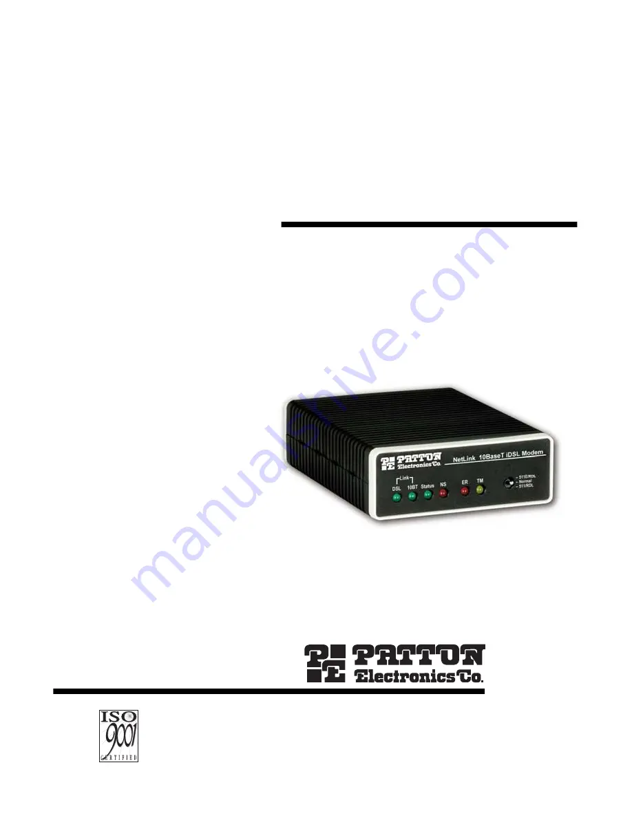
MANUAL
MODEL 1082/I and1082/144/I
iDSL Modem with 10Base- T Interface
SALES OFFICE(301) 975-1000TECHNICAL SUPPORT(301) 975-1007
Part# 07M1082/I-BDoc# 033181UBRevised 7/13/01
An ISO-9001
Certified
Company
C E R T I F I E D
Страница 1: ...ODEL 1082 I and 1082 144 I iDSL Modem with 10Base T Interface SALES OFFICE 301 975 1000 TECHNICAL SUPPORT 301 975 1007 Part 07M1082 I B Doc 033181UB Revised 7 13 01 An ISO 9001 Certified Company C E R...
Страница 2: ...RDL Request 14 Configuring DIP switch S2 15 Switches S2 1 19 2 kbps or 144 kbps Synchronous Rate Enable 15 Switch S2 2 Front Panel Switch Disable 16 Switches S2 3 S2 6 S2 7 and S2 8 Reserved 16 5 0 In...
Страница 3: ...3 A 8 Connectors 25 A 9 Power 25 A 10 Temperature Range 26 A 11 Altitude 26 A 12 Humidity 26 A 13 Dimensions 26 A 14 Weight 26 B Model 1082 I Factory Replacement Parts and Accessories 27...
Страница 4: ...suant to Part 15 of the FCC Rules These limits are designed to provide reasonable protection against harmful interfer ence when the equipment is operated in a commercial environment This equipment gen...
Страница 5: ...number may be obtained from Patton Electronics Technical Service at Tel 301 975 1007 E mail support patton com URL www patton com Note Packages received without an RMA number will not be accepted Patt...
Страница 6: ...and removes MAC addresses Point to point distances up to 5 miles all data rates on 24 AWG twisted pair HTTP SNMP Manageable as CP Customer Premises Unit with 1092ARC CO Central Office Rack Card and 10...
Страница 7: ...ernally accessible configuration switches As a symmetric DSL modem the1082 offers the same data rates in both directions over a single pair of regular telephone lines using 2BIQ modulation The 1082 co...
Страница 8: ...ch of the network layer protocols have been configured datagrams from the established network layer protocol can be sent over the link The link will remain configured for these communications until ex...
Страница 9: ...ng for the above example Authentication is optional under PPP In a point to point leased line link incoming customer facilities are usually fixed in nature therefore authen tication is generally not r...
Страница 10: ...ers over a serial interface Figure 3 illustrates transparent bridging between two routers over a serial interface s0 Bridging will occur between the two Ethernet inter faces on router A e0 and e1 and...
Страница 11: ...URING THE HARDWARE DIP SWITCHES Using a small flat tip screwdriver remove the protective cover located on the underside of the Model 1092 see Figure 4 Figure 4 Removing the cover to access DIP switche...
Страница 12: ...switches S1 1 through S1 8 Detailed descriptions of each switch follow the table S1 S2 1 2 3 4 ON 5 6 7 8 1 2 3 4 ON 5 6 7 8 1 2 3 4 ON 5 6 7 8 Push toggle up for ON position Switch toggle Push toggle...
Страница 13: ...operate at these rates set Switches S1 1 and S1 2 both to the OFF position and Switch S2 1 to the ON position see Configuring DIP switch S2 on page 152 for a description of Switch S2 1 If the S2 1 sw...
Страница 14: ...Model 1082 144 I Note The Remote Digital Loopback RDL will not work for 144 kbps You must first set the units to 128 kbps or slower to use the RDL S1 6 S1 7 Clock Mode Description On On Internal Syste...
Страница 15: ...144 kbps set switches S1 1 and S1 2 to the OFF position and switch S2 1 to ON see section Configur ing DIP Switch S1 on page 12 144 kbps data rate is only available on the Model 1082 144 I 19 2 kbps...
Страница 16: ...t Panel Switch Disable Use switch S2 2 to enable or disable the front panel toggle switches Switches S2 3 S2 6 S2 7 and S2 8 Reserved S2 2 Setting On Disable the front panel switches Off Enable the fr...
Страница 17: ...nits operate as a pair Both units at the end of the twisted pair DSL span must be set for the same DTE rate To function properly the Model 1082 needs one twisted pair of metallic wire This twisted pai...
Страница 18: ...and connect the wires as shown in Figure 8 Figure 8 Connecting 10Base T Ethernet port to PC 5 3 CONNECTING 10BASE T ETHERNET PORT TO HUB DCE The 10Base T interface is configured as DTE Data Terminal...
Страница 19: ...a male IEC 320 power entry connector This power supply connects to the Model 1082 I by means of a barrel jack on the rear panel Many interna tional power cords are available for the universal power su...
Страница 20: ...082 I Refer to Figure 10 below to make the proper connection Figure 10 Power adapter WARNING There are no user serviceable parts in the power supply section of the Model 1082 I Contact Patton Electron...
Страница 21: ...ion on page 19 and ensure that the unit is connected to the appropriate power source 6 2 LED STATUS MONITORS The Model 1082 I and Model 1082 144 I feature six front panel LEDs that monitor connections...
Страница 22: ...oo large 6 pulses WAN receive frame s not octet aligned 7 pulses WAN receive frame s aborted 8 pulses Detected WAN receive frame s with CRC 9 pulses Detected LAN receive frame s too large 10 pulses De...
Страница 23: ...inal will appear on the local terminal screen after having been passed to the remote Model 1082 and looped back Figure 12 Remote digital loop Table 2 LED configurations LOCAL REMOTE 10Base T DSL Statu...
Страница 24: ...he 511 RDL toggle switch on the front panel of the 1082 I and move it DOWN This initiates the RDL and sends a 511 pattern into the loop If any errors are present the local modem s red ER LED will blin...
Страница 25: ...ror rate pattern 511 511E pattern generator and detector with error injection mode Local Line Loopback and Reomote Dig ital Loopback activated by front panel switches or via serial interface A 7 LED S...
Страница 26: ...0 TEMPERATURE RANGE 32 122 F 0 50 C A 11 ALTITUDE 0 15 000 feet 0 4 572 meters A 12 HUMIDITY 5 95 non condensing A 13 DIMENSIONS 4 125W x 1 625H x 6 0D in 10 5W x 4 1W x 15 2D cm A 14 WEIGHT 2 01 lbs...
Страница 27: ...dule 08055DCUI 100 240VAC 5V 5 reg DC 2A Universal Input Adapter 0805EUR European Power Cord CEE 7 A 0805UK United Kingdom Power Cord D 0805US American Power Cord K 0805AUS Australia New Zealand Power...
Страница 28: ..._________________________________________ _________________________________________________________ _________________________________________________________ __________________________________________...