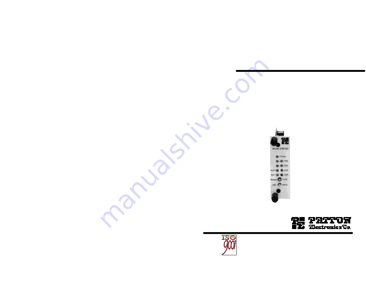
manualshive.com logo in svg
background image

USER

MANUAL

MODEL 2701RC Series

NetLink-E1™
E1/Fractional E1 CSU/DSU
Rack Card

SALES OFFICE
(301) 975-1000
TECHNICAL SUPPORT
(301) 975-1007
http://www.patton.com

Part# 07M2701RC-B
Doc# 086131UB
Revised 03/09/01

C E R T I F I E D

C E R T I F I E D

An ISO-9001

Certified Company

Содержание 2701RC

Страница 1: ...tLink E1 E1 Fractional E1 CSU DSU Rack Card SALES OFFICE 301 975 1000 TECHNICAL SUPPORT 301 975 1007 http www patton com Part 07M2701RC B Doc 086131UB Revised 03 09 01 C E R T I F I E D C E R T I F I...

Страница 2: ...ot cover customer damage abuse or unauthorized modification This product contains no serviceable parts therefore the user shall not attempt to modify the unit in any way If this product fails or does...

Страница 3: ...ES Terminates E1 FE1 Circuits over a 4 Wire RJ 48C interface Connects to standard CPE Serial Interfaces Common Framed nx64 rates up to1984 kbps G 704 Unstructured Rate of 2 048 Mbps G 703 G 703 or G 7...

Страница 4: ...change the switch settings to the desired settings When you turn the unit on again the unit will be set up with the selected switch settings Switch S1 1 through S1 8 A detailed description of each sw...

Страница 5: ...s the unit is forced into G 703 mode and it transmits user data on all 32 time lots There is no framing information therefore the CRC4 MF S2 2 switch is ignored In all other rate settings the unit em...

Страница 6: ...V 54 Loopback is disabled the unit will not be able to send or respond to V 54 or CSU loopback commands The duration of the loopback is limited by the loopback timeout setting S2 4 Option Off RDL Resp...

Страница 7: ...strap can either be on pegs 1 and 2 or on pegs 2 and 3 Sections 3 2 1 3 2 2 and 3 2 3 describe the strap locations and possi ble settings for each rear card 3 2 1 Model 1001RCM12548C Strap Settings F...

Страница 8: ...igure 6 shows the strap location for the Model 1001RCM13448C M 34 rear card This strap determines whether Signal Ground and Frame Ground will be connected The table below provides an overview of inter...

Страница 9: ...ap links Signal Ground and frame ground through a 100 ohm resistor In the open position signal ground is disconnected from frame ground JB4 Position 1 2 SGND and FRGND Connected Position 2 3 SGND and...

Страница 10: ...no parity Local echo off ANSI or VT 100 emulation 4 Here is an example of a terminal emulator setup session In normal font are the various parameter types In bold type are the values that should be us...

Страница 11: ...inal can generate is 16 characters 7 The NetLink E1 will then display the Main Menu screen 3 3 3 Introduction to Main Menu After entering the password you may access all of the system s functions and...

Страница 12: ...s a Service Information screen in case you need technical assistance from Patton Save Changes Once you have configured the unit to your satisfaction you can save the changes permanently by exe cuting...

Страница 13: ...en connect ing to a carrier s network In this mode the unit recovers the clock from the received signal and uses it to transmit data In this way the unit remains synchronized to a master clock In camp...

Страница 14: ...pback timeout setting While V 54 is being activated user data is overwritten Default Config Source Switch default Options EEPROM Switch The Model 2701RC can be initialized via the configuration in the...

Страница 15: ...nd ing a pattern Local loopback is disabled LocP The Model 2701RC is in Local Loopback mode and is sending a test pattern Remote Loop Idle default The Remote Digital Loopback RDL test checks the perfo...

Страница 16: ...when Remote Loop is selected by the front panel switches S2 3 RDL Type Off Initiate a V 54 RDL loop when selected On Initiate a CSU loopback when selected Test Pattern Idle default Options Idle or Se...

Страница 17: ...s 00 15 fifteen minutes 00 30 thirty minutes default setting 00 45 forty five minutes 01 00 one hour 01 30 90 minutes 02 00 two hours 03 00 three hours NEVER forever the unit will remain in loopback w...

Страница 18: ...n a 19 rack Sturdy front handles allow the Model 1001R14 to be extracted and transported conveniently 4 1 1 The Rack Power Supply The power supply included in the Model 1001R14 rack uses the same mid...

Страница 19: ...ting toward the front panel of the Model 2701RC pc board 5 Push the Interface Driver Board gently onto the socket and re install into the 1001 rack 4 3 INSTALLING THE MODEL 2701RC INTO THE CHASSIS The...

Страница 20: ...d is equipped with dual female BNCs TX and RX for connection to a 75 ohm dual coax G 703 network interface 5 0 OPERATION Once the NetLink E1 is installed and configured properly it is ready to place i...

Страница 21: ...urns off when the unit is not powered 5 2 LOOP V 54 TELCO DIAGNOSTICS The NetLink E1 offers three V 54 loop diagnostics and is com patible with two Telco loop diagnostics Use these diagnostics to test...

Страница 22: ...to Appendix D c Set the front panel switch to Remote 2 Perform a bit error rate test BERT using the internal V 52 generator as described in Section 5 3 or using a separate BER Tester If the BER test i...

Страница 23: ...ohm available when using Patton Model 1001RCM11575 rear card DTE Interface V 35 DCE Orientation X 21 DCE or DTE orientation RS 530 RS 232 10Base T Ethernet Line Coding Selectable AMI or HDB3 Line Fram...

Страница 24: ...35 Interface with M 34F RJ48C Rear Card 1001RPEM RAC 120 240V Rear Power Entry Module 1001RPEM RAC 120 240V Rear Power Entry Module 1001RPSM RUI 120 240V Front Power Supply Module 1001RPEM RDC DC Rea...

Страница 25: ...Ground Shield B SGND Signal Ground D CTS DCE Source E DSR DCE Source Always On F CD DCE Source L LL Local Loop DTE Source M TM Test Mode Indicator DCE Source N RL Remote Loop DTE Source P TD Transmit...

Страница 26: ...a A DTE Source 15 TC Transmitter Clock B DCE Source 16 RD Receive Data A DCE Source 17 RC Receiver Clock A DCE Source 18 LL Local LIne Loop 19 RTS Request to Send B DTE Source 20 DTR Data Terminal Rea...

Отзывы: