Patterson RC Скачать руководство пользователя страница 4


1


SECTION I  

GENERAL INFORMATION  

This manual covers the installation, operation and maintenance of Patterson Pump vertical inline pumps.  
The  pump  is  a  centrifugal,  single  stage  close-coupled  type.   When  properly  installed  and  when  given 
reasonable  care  and  maintenance,  centrifugal  pumps  should  operate  satisfactorily  for  a  long  period  of 
time.   Centrifugal  pumps  use  the  centrifugal  force  principal  of  accelerating  the  liquid  within  a  rotating 
impeller, and then collecting it and converting it to pressure head in a stationary volute.   

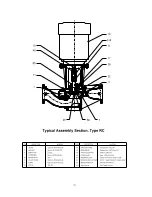
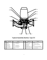
The pump consists of two assemblies:  

1. 

Volute assembly or stationary part  

2. 

Rotating element or moving part   

The  back  pullout  design  casing  allows  removal  of  the  impeller  and  rotating  element  without  disturbing 
suction  and  discharge  piping.   The  suction  and  discharge  flanges  are  on  a  common  centerline  180 
degrees apart.   Suction and discharge flanges are drilled and tapped for gauge connections.   The volute 
is  drilled  and  tapped  on  the  underside  for  complete  pump  drain.  Casing  wear  rings  are  provided  as 
standard equipment.      

SECTION II  

STORAGE & PROTECTION  

All  pumps  are  shop  serviced  and  ready  for  operation  when  delivered,  but  there  is  occasions  when 
considerable  time  elapses  between  the  delivery  date  and  the  time  the  pump  is  put  into  operation.  
Equipment, which is not in service, should be kept in a clean, dry area.   If equipment is to be stored for 
long  periods  of  time  (six  months  or  more),  the  following  precautions  should  be  taken  to  insure  that  the 
equipment remains in good condition.   

1. 

Unpainted-machined  surfaces,  which  are  subject  to  corrosion,  should  be  protected  by 
some corrosive resistant coating.  

2. 

The shaft should be rotated 10 to 15 revolutions by hand periodically in order to spread 
the  lubricant  over  all  the  bearing  surfaces.   Suitable  intervals  are  from  one  to  three 
months, depending on atmospheric conditions, etc.  In order to insure that the pump shaft 
does not begin to sag, do not leave the shaft in the same position each time.  

3. 

Space  heaters  on  motors  and  controllers  should  be  connected  and  fully  operable  if 
atmospheric  conditions  approach  those  experienced  in  operation.   Consult  instruction 
manuals  for  other  precautions  concerning  storage  of  individual  components  of  pumping 
unit.  

4. 

Fresh  lubricant  must  be  applied  to  bearings  upon  removal  of  equipment  from  storage.  
Refer to motor manual.   

Содержание RC

Страница 1: ...ANCE MANUAL For VIL VERTICAL INLINE PUMPS Types RC CC and CS PATTERSON PUMP COMPANY A SUBSIDIARY OF THE GORMAN RUPP COMPANY PO Box 790 9201 Ayersville Road Toccoa Georgia 30577 Telephone 706 886 2101...

Страница 2: ...possible injury Among the many considerations personnel should be instructed to avoid contact with rotating parts avoid bypassing or rendering inoperative any safeguards or protective devices avoid e...

Страница 3: ...Mounting 2 3 3 Piping 2 3 4 Wiring and Controls 2 SECTION IV Operation 4 1 Starting 2 4 2 Shutdown 3 SECTION V Maintenance 4 SECTION VI Repairs Replacement 6 1 Disassembly 5 6 2 Cleaning 5 6 3 Inspec...

Страница 4: ...E PROTECTION All pumps are shop serviced and ready for operation when delivered but there is occasions when considerable time elapses between the delivery date and the time the pump is put into operat...

Страница 5: ...e piping into place by tightening the flange bolts Pipes should be supported near the pump 3 4 Wiring and Controls The electric motor power supply connections mush conform to national and local codes...

Страница 6: ...osed as required by your specific requirements Start driver Open discharge valve slowly when the pump is up to speed CAUTION Overheating and or loss of prime will result if the pump is operated agains...

Страница 7: ...Inspect or service at the indicated calendar time or run time interval whichever comes first Routinely Monthly 2000 hours or 3 months 4000 hours or 6 months 8000 hours or 12 months Unusual noise Unus...

Страница 8: ...from the motor shaft by turning the impeller screw 26 counterclockwise 4 Mechanical seal 65 may now be removed Type RC To Remove Mechanical Seal 1 Remove bolting holding rigid coupling 314 to motor sh...

Страница 9: ...mbedded particles Replace if defective in any way Mount shaft between lathe centers and check eccentricity for entire length of the shaft Eccentricity should not exceed 002 inches Bearing surfaces sho...

Страница 10: ...Delivered Air leaks in suction pipe or stuffing boxes Speed too low Discharge head higher than anticipated Impeller partially plugged up Obstruction in suction line Mechanical defects casing rings wo...

Страница 11: ...inds Rubbing due to foreign matter in the pump between the case rings and the impeller Pump Vibrates Misalignment Foundation not sufficiently rigid Impeller partially clogged Mechanical defects bent s...

Страница 12: ...ription 7 Casing Ring 14 Shaft Sleeve Type CC only 65 Mechanical Seal Gasket casing CONTINUOUS DUTY Number Description 2 Impeller 6 Shaft Types RC and CS only 7 Casing Ring 14 Shaft Sleeve Type CC onl...

Страница 13: ......

Страница 14: ......

Страница 15: ......

Страница 16: ...13 Notes...

Отзывы: