background image

Wireless  Data  Acquisition  System  Instruction  Manual 


46


■ When Connecting to LAN 

Step 

Item 

References 

Prepare required equipment and create 
maintenance environment 

R

efer to 

  "5.2(2)

  Maintenance System 

Configuration (using the power supply input kit) 


Application for outputting wireless settings and 
signal tower information to CSV 

Refer to 

  "Downloading WDS-WIN 01 from our 

website" 

Communication settings between WDR and 
Maintenance PC 

Refer to 

  "WDS-WIN01 Instruction Manual". 

WDT setup 

WDR setup 


(4) 

WDR DIP Switch Operations 


DIP Switch Operations 


CAUTION 


Prohibited


Do not use excessive force on this product. Failure to follow this instruction will result in equipment 
damage. 


Do not use sharp tipped objects with this product. Operation may become impossible as scratches 
develop on switches and switch contacts are interfered with. 

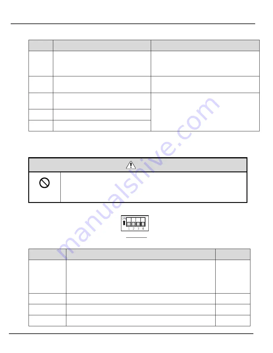
  DIP switches for this product are inside the main unit. 


DIP switch 

  DIP Switch Settings 

Switch number 

Description 

Initial settings 

Initialize LAN communication settings 

OFF 

• OFF 

Normally use with this setting OFF. 

• ON 

Initializes LAN communication settings. 

Refer to 

  "7.2(5) Initializing WDR LAN communication settings" 

OFF (static) 

OFF 

OFF (static) 

OFF 

OFF (static) 

OFF 


Содержание WDR-LE-Z2

Страница 1: ...e performed by a professional contractor if construction work is involved Prior to installation read this manual thoroughly before using this product to ensure correct use Re read this manual before c...

Страница 2: ...DT 16 2 WDR 17 6 Installation 19 6 1 Before Installation 19 1 What is the WD Wireless Network 19 2 About Grouping and ExtendedPanID 21 3 About the MAC Address 22 4 How many WDT you can connect to WDR...

Страница 3: ...Related to Wireless Data Transmission 48 2 Functions Related to Signal Tower Input 51 3 Install Initialize and Change Settings Functions 54 9 Replacement and Optional Parts 56 9 1 Replacement Parts 56...

Страница 4: ...structions are ignored WARNING This symbol indicates Failure to follow the instructions may lead to death or serious injury CAUTION This symbol indicates Failure to follow the instructions may lead to...

Страница 5: ...ailure to follow these instructions could result in fire or electric shock Do not use this product when there is condensation Failure to follow these instructions could result in fire or electric shoc...

Страница 6: ...ght Locations subject to shock and vibration Near heating appliances Environments where there is dust iron powder and so on Places near fire or environments with high temperatures and humidity Locatio...

Страница 7: ...ion Disposing this product When disposing of this product follow the rules and regulations on how to handle recyclable materials as outlined in your community About this manual The contents of this ma...

Страница 8: ...em Instruction Manual 8 2 Contents 2 1About the Contents 1 WDT 4LR Z2 WDT 5LR Z2 WDT 6LR Z2 Product 1 unit Instruction Manual digest version 1 copy 2 WDR LE Z2 Product 1 unit Ferrite core 1 Instructio...

Страница 9: ...Signal Tower LR5 WDT 6LR Z2 Compatible LR Series Signal Tower LR6 LR Signal Tower Models This product Compatible LR Series Signal Tower Model Model Size Rated Voltage WDT 4LR Z2 LR4 02 40 24 VDC LR4 M...

Страница 10: ...ireless Data Acquisition System Instruction Manual 10 4 Part Names and Dimensions 4 1About Part Names and Dimensions 1 WDT transmitter Part Names Part Dimensions Front View units mm Front View units m...

Страница 11: ...n System Instruction Manual 11 2 WDR receiver Part Names main unit Front View Bottom View Part Names inside the main unit Front View inside the main unit Part Dimensions Front View Front View inside t...

Страница 12: ...multiple WDT up to 30 units Signal Tower information Status of the signal tower from which the WD system collects data WDT Transmitter on a WD wireless network The WDT collects signal tower informatio...

Страница 13: ...ation items Models WDT 1 to 30 units 1 per receiver WDT 4LR Z2 or WDT 5LR Z2 or WDT 6LR Z2 WDR 1 to 20 units 2 WDR LE Z2 WDS 1 WDS WIN01 Host PC 3 1 1 For more information refer to 6 1 4 How many WDT...

Страница 14: ...his Product WDT 6LR Z2 This Product Power supply input kit option 1 WDX 4LRB WDX 5LRB WDX 6LRB AC Adaptor option 1 ADP 001 WDR 1 WDR LE Z2 WDS 1 WDS WIN01 Maintenance PC 1 LAN Cable 2 3 1 USB Cable 4...

Страница 15: ...sted 2 Socket Communication Pattern 1 CSV Assisted WD System Transmit Signal Tower information WDS Save loaded signal tower information as CSV data Visualization Application Software Visualization of...

Страница 16: ...types of signal tower information Refer to 8 1 1 Select Format of Signal Tower Information Maintain Signal Tower Status When a transmission failure occurs between the signal tower signal input and the...

Страница 17: ...ecific command from the host PC the indicator flashes blue for approximately 10 seconds Refer to 8 1 3 Display WDT Call Display WDT MAC address A label on the body of the WDT identifies its MAC addres...

Страница 18: ...wer supply input status Green light Power ON light off Power OFF Initialize Network Settings Function for resetting the LAN network settings to its factory default Select by toggling a DIP switch on t...

Страница 19: ...f the frequencies used overlap the WD wireless network could experience transmission delays and other communication issues The wireless communication is encrypted The encryption standard used is AES C...

Страница 20: ...3 2 415 2 CH14 2 420 2 CH15 2 425 2 CH16 2 430 2 CH17 2 435 2 CH18 2 440 2 CH19 2 445 2 CH20 2 450 2 CH21 2 455 2 CH22 2 460 2 CH23 2 465 2 CH24 2 470 2 CH25 2 475 2 CH26 2 480 2 Example Wireless Chan...

Страница 21: ...and wireless channels for devices in multiple groups If there are multiple channels available for selection you should use separate wireless channels for each group By distributing groups over multipl...

Страница 22: ...to WDR The number of WDT units you can connect to a WDR is limited by how often signal tower information is sent to the WDR Limit the number of WDT so that the WDR processes an average of about 120 ti...

Страница 23: ...er to 6 2 1 2 Distance Between Devices The recommended distance between all WDT and WDR is within line of sight 3 Line of sight between each device WDR WDT To ensure good line of sight the location sh...

Страница 24: ...es power supplies and industrial equipment Noise from microwave ovens fluorescent lamps and so on Surrounding obstacles Interference caused by fading of own radio waves Various obstacles wall floor ce...

Страница 25: ...referred to as the Fresnel Zone is required The Fresnel zone is a three dimensional space whose size is estimated as follows Line of sight L 20 m Fresnel zone diameter D about 1 6 m Line of sight L 10...

Страница 26: ...nformation for the settings below prepared beforehand Information required Description Information about the equipment to connect Equipment name and other identifiable equipment information Informatio...

Страница 27: ...WDS WIN01 for equipment settings Install WDS WIN01 on the maintenance PC and set up the equipment For using WDS WIN01 refer to the WDS WIN01 Instruction Manual The setup procedure is as follows Step...

Страница 28: ...fer to 7 2 1 Mounting the WDR 2 WDR wiring procedure Refer to 7 2 2 WDR Wiring 3 Check the Connection Between WDT and WDR Step Item References 1 Check the WDT wireless status Refer to 8 1 3 Display Co...

Страница 29: ...e to follow this instruction could result in a short circuit Supply only the correct power direct current or alternating current and use the proper voltage Failure to follow this instruction could res...

Страница 30: ...re to follow this instruction could result in a short circuit 2 Attaching and Detaching the WDT WARNING Mandatory Before any work is done disconnect the power CAUTION Prohibited Do not apply excessive...

Страница 31: ...ED unit it is difficult to assess the status shown by the lamp on this product CAUTION Prohibited Do not detach multiple connected units except head cover from this product or the body unit When detac...

Страница 32: ...Wireless Data Acquisition System Instruction Manual 32 Attaching the WDT to the LR Series Signal Tower Attaching WDT 4LR Z2 Attaching Detaching Positioning Mark...

Страница 33: ...Wireless Data Acquisition System Instruction Manual 33 WDT 5LR Z2 WDT 6LR Z2 Attaching Detaching Positioning Mark Locked Unlocked...

Страница 34: ...T to the LR series signal tower Attach or detach units in the prescribed order beginning with 1 Detach and attach units one at a time The following are the steps for detaching the WDT from the LR seri...

Страница 35: ...onally depending on how it is removed the tab may come out of the groove as shown in Figure 1 when detaching this product from the body unit If the product is attached again while the tab is still in...

Страница 36: ...imple counter settings Refer to 8 1 1 Selecting the signal wire for a simple counter Transmission mode Refer to 8 1 1 Functions Related to Wireless Data Transmission 1 For this product s settings use...

Страница 37: ...itch number Description Initial settings 1 Initialize setting values OFF OFF Normally use with this setting OFF ON Initializes the value for various settings Refer to 7 2 5 Initialization Process 2 Me...

Страница 38: ...play Communication Quality 6 Initializing the WDT Initialization process Follow the instructions to run initialization Step Item 1 Turn on DIP switch 1 on the product 2 Turn on the power After a few s...

Страница 39: ...lfunction Turn off the power before performing any electric wiring or product installation Failure to follow this instruction could result in electric shock When working in narrow or high places pay a...

Страница 40: ...en using the wiring access from the rear of the unit cut open the cover colored with nippers 3 When wiring access insufficient bottom When using the wiring access from the bottom of the unit and the c...

Страница 41: ...ock or the DC jack Failure to follow this instruction could result in equipment failure Do not connect the USB cable and LAN connector at the same time WDR will not operate properly NOTICE Use 28 14 A...

Страница 42: ...ectors When using a contact terminal block At this point do not turn on the power Wrap the lead wire around a ferrite core 2 Insert the LAN cable into the WDR main unit s LAN connector LAN cable is no...

Страница 43: ...e to the WDR main unit USB cable is not included Power is supplied via the bus for the USB cable 2 Insert the USB cable to the PC NOTE On the first USB connection the Found New Hardware wizard starts...

Страница 44: ...TE Contact capacity is 24 VDC 500 mA When using contact outputs you can control them with contact control commands For information about contact control commands refer to Application Notes CAUTION You...

Страница 45: ...N communication LAN communication settings Refer to 6 3 1 Setup Information Required equipment For information on system configuration when setting up the equipment refer to 5 2 2 Maintenance System C...

Страница 46: ...WDR DIP Switch Operations DIP Switch Operations CAUTION Prohibited Do not use excessive force on this product Failure to follow this instruction will result in equipment damage Do not use sharp tipped...

Страница 47: ...network settings to their default values Step Item 1 Power down the WDR 2 Turn on DIP switch 1 on the product 3 Power up the WDR The power LED green lights up 4 Wait for the output LED red to light u...

Страница 48: ...ignal Tower information Description Signal display Buzzer Red Amber Green Blue White Status light on flashing light off sound no sound Only when extended format is selected Relationship between the un...

Страница 49: ...o the WDR for transmitting the information A dense mesh status increases communication redundancy Mesh Status Simple Counter Function By using a pulse input on a single signal wire count up the number...

Страница 50: ...al wire for a simple counter Use one of the following to select the signal wire Signal wire selection method DIP Switch Wire used by the simple counter Using a DIP switch on the unit Blue fixed Using...

Страница 51: ...put repeatedly changes light on to light off to light on to light off and so on the result is flashing and information is transmitted You can select from 3 different time periods in WDS WIN01 before f...

Страница 52: ...square brackets represent buzzer operation Setting Determination Description Change in state Operation result Normal Light on Light off light on Light off Light on light off Flashing Flashing Light o...

Страница 53: ...anges when they occur faster than 100 ms When using normal determination and you need to change the input state of multiple signal towers at the same time the interval between these state changes need...

Страница 54: ...used as a repeater for communication Red pulse Connection is not good with any WDR or WDT in the WD wireless network Red light Product is waiting to join the WD Network Pulse is where the lamp fades b...

Страница 55: ...nual 55 Settings Item Initial settings ExtendedPanID 0000 0000 0000 0000 Frequency Channel Select all Determine signal tower input Flashing medium Power supply Power line Transmission mode Immediate t...

Страница 56: ...ustomer for exchange or replacement 1 WDT WDT 4LR replacement parts WDT 5LR replacement parts WDT 6LR replacement parts O ring 40 O ring 50 O ring 60 5 pieces 5 pieces 5 pieces 9 2Optional Parts The f...

Страница 57: ...t it may take some time to complete the connection Check the indicator again after about 5 minutes Check if the WDR is working properly The ExtendedPanID in the WDR must match the wireless channel set...

Страница 58: ...representative Contact output does not output Wire correctly and check the operation Send the correct command The host and USB are connected but communication does not work Select the correct port and...

Страница 59: ...e Ambient Temperature 20 C to 60 C Storage Ambient Humidity 85 RH or less no condensation Mounting Location Indoors Mounting Direction Upright Protection Rating IP65 IEC 60529 NEMA TYPE 4X 13 Mass 70...

Страница 60: ...10 C to 60 C no condensation Storage Ambient Temperature 20 C to 70 C free from freezing Relative Humidity 85 RH or less no condensation Mounting Location Indoors Mounting Method Horizontal installat...

Страница 61: ...Wireless Data Acquisition System Instruction Manual 61...

Отзывы: