*
Denotes Normal Wear Item.
▲
Apply Loctite 242 (Blue) Part No.095300
**
Make sure Warning Label (900496) is properly affixed replace if necessary. Label is available at no charge through the
Service Dept.
➔
Denotes Change
1
900356
1
Grille
2
900455
1
Filter
3
008738
4
Socket Head Cap Screw, 10-24 x 1-1/4
4
008388
7
Flat Washer #10
5
900410
1
Cap Assembly
6
404427
3
Screw, Taptite, B-32 x 5/8
7
006562
3
Washer #8
8
900575
1
Circuit Board Assembly
9
900573
1
Fan Motor with Mount
10
900468
1
Washer
11
900287
1
Spark Plug Assembly
12
401356
1
Sleeve, Motor
15
403146
1
Stem Adapter (Yellow)
16
900004
1
Cylinder Head
*17
404700
2
O-Ring
18
403167
1
Fan Blade Assembly
19
900583
1
Removable spark Plug Wire
20
900280
1
Spark Unit Assembly
21
404601
1
Head Switch Assembly
22
404490
1
Trigger Switch Assembly
23
900232
1
Cable Clamp
25
900094
2
Screw 10-32 x 5/8
26
006546
2
Internal Lockwasher #10
27
404432
1
Bushing
28
900357
1
Actuator
29
404433
1
Pin
30
900415
1
Actuator Assembly
31
900405
1
Self Clenching Nut
32
900944
1
Handle Assembly, Right Side
**
33
900496
1
Warning label
34
900576
1
Nameplate
35
900311
1
Contact Positive
36
900312
1
Contact Negative
37
900943
1
Handle Assembly, Left Side
38
900508
1
International Label
40
900453
3
Thread Forming Screw, 8-16 x 7/8
41
900289
1
Belt Hook
42
403107
1
Screw, 8-32 x 1 1/2
43
403082
3
Washer, .189 x .312 x .040
44
900942
1
Bushing
45
401450
2
Pad
46
404385
1
Light Pipe
47
402201
2
Screw, Phillips Head, 2-56 x 5/8
48
401395
1
Spring
49
900358
1
Trigger
50
900336
1
Contact Wire Assembly
51
900941
1
Nut 8-32
52
404702
2
Screw, Thread 6-32 x 3/8
53
900329
1
Spring, Cover
54
900328
1
Spring, Negator
55
900350
1
Lever, Quick Clear
56
900301
1
Follower
57
900302
1
Cover
58
900166
1
Spring
59
900338
2
Screw 10-32 x 1/2
61
900332
1
Hub
62
900303
1
Cover, Moveable
63
900326 2
Wear Strip
64
900417
1
Rail Assembly
65
900407
2
Socket Head Cap Screw 10-32 x 5/16
66
004174
3
Screw 10-24 x 7/8
67
900335
1
Spring, Quick Clear
68
900412 1
Nose Assembly
69
900342
1
Mounting Ring
70
900353
1
Pivot Pin
71
900324
1
Front Guide
72
403104
1
Air Dam
73
403100
1
Combustion Chamber Assembly
74
403099
1
Retaining Ring, Piston
*75
403098
1
Piston Ring
76
403095
1
Piston Driver Blade Assembly
*77
403094
1
Bumper
78
900416
1
Upper Probe Assembly
79
403084
1
Sleeve and Midcheck Ring Assembly
80
403089
1
Seal Washer
81
403090
2
Wave Washer
82
403092
2
Retaining Ring, Midcheck
83
403091
1
Muffler
84
404339
1
Spring, Chamber Return
85
403106
1
Cage
86
900651
2
Label, Logo
87
900323
1
Probe, Lower
88
900411
1
Housing Assembly
89
900352
1
Tip
90
900182 2
Washer, Trigger
91
900382
1
Back Plate Insert
92
403713 3
E-Ring, Retaining
93
404613
1
Cable Tie
94
900164
1
Ring
95
900331
2
Insert, Handle
96
900341
2
E-Ring
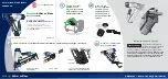
PARTS LEGEND
IM250 F-16 TYPE II,
900400
▲
▲
1. WEAR EYE AND EAR PROTECTION.
2. ALWAYS ASSUME THE TOOL IS ‘LOADED’.
3. OPERATE THE TOOL ONLY ON THE WORK
SURFACE.
4. NEVER REMOVE OR DISABLE THE WORK
CONTACTING ELEMENT.
This device helps reduce the possibility of accidental
fastener discharge by preventing the tool from
operating until it is completely against the work surf ace.
NEVER operate the tool if t he work contacting element
is not working properly.
SAFETY INSTRUCTIONS
5. ALWAYS POINT THE TOOL AWAY FROM YOURSELF
AND OTHERS WHEN CLEARING JAMS OR
REMOVING FASTENERS.
Pull the follower back and latch. Tip the tool nose up
slightly and fasteners should slide out of the magazine. If
fasteners are jammed, refer to the appropriate section of
the operating manual.
6. NEVER ATTEMPT TO OPERATE THE IMPULSE TOOL
IF PARTS ARE LOOSE, DAMAGED OR
MISSING.