®
Model No.EM-8678A
Equipment Setup
5
Appendix A: Specifications
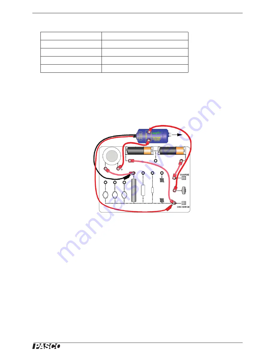
Appendix B: Typical Circuit Diagram
The Charge/Discharge Circuit board was designed to allow the user flexibility in measurement and experimenta-
tion. The lower portion of the board contains a built-in copper circuit with a lacquer finish. The upper half of the
board provides multiple connection points for various setup options. (Note: The board does not contain a
series-parallel circuit.)
Diagram: Typical Setup for Demonstrating Ohm’s Law
By allowing the batteries to charge a capacitor connected to a resistor, this setup may be used to study Ohm’s law
in “real time” (that is, seeing the current and voltage dynamically change). When the switch is moved to the
charge position, the battery charges the capacitor. When the switch is moved to the discharge position, the capac-
itor discharges through the resistor. In the PASCO data acquisition software, plot the voltage vs. the current
during “Discharge” for each separate run. The slope of the graph is resistance. To see the effect of varying the
resistance on the voltage discharge rate, the student can switch the lead connections to different resistors.
Using the Data Acquisition Software
•
For example, in the PASCO Capstone software, click the “Hardware Setup” icon in the Tools palette to open
the “Hardware Setup” panel. Confirm that the Voltage-Current Sensor icon appears with the interface’s icon.
•
Create a graph display. Select “Voltage” for the vertical axis and “Current” for the horizontal axis. (The
slope of this graph will be the resistance.)
•
Move the switch to the “Charge” position and let the capacitor charge for 20 to 30 seconds.
•
Next, move the switch to the “Discharge” position and click ‘Record’ to begin collecting data.
•
When the current reaches zero, click ‘Stop’ and move the switch to the middle position.
Item
Information
Capacitor
1.0 farad, 5 volt maximum
Resistors
10 ohm, 33 ohm and 100 ohm, 5 volt maximum
Light Bulbs
3 volt maximum
Board
18.3 by 13 centimeters composed of fiberglass
Note: The appearance of the
Charge/Discharge Circuit
may vary slightly.
To PASCO
Interface


