background image


INSTRUCTION REF: IN191          
ISSUE No.  3 
DATE   18.08.15 
Page 11 of 17 


www.parry.co.uk 


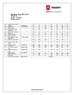
PARTS LIST  
 

No. 

PART DESCRIPTION 

PART CODE 

PC 

140 

PC 

140G 

PC 

140B 

PC 

140GB 

PC 

140GR 

PC 

140 

GRBF 

PC 

140 

GRB 

Top 

X 1 

X 1 

X1 

X 1 

X1 

X1 

X1 

Branding Plate (C/W 
Light Cut Out) 

N/A 

N/A 

N/A 

X 1 

N/A 

N/A 

X1 

2a 

Branding Plate 

N/A 

X1 

X1 

N/A 

X1 

X1 

N/A 

Branding Perspex 

PCPERSPEX 

N/A 

N/A 

N/A 

X 1 

N/A 

N/A 

X1 

3a 

Branding Perspex 

PCPERSPEXSM 

N/A 

N/A 

X1 

N/A 

N/A 

X1 

N/A 

SSU Starter 

PDSSU 

N/A 

N/A 

X1 

X 1 

N/A 

X1 

X1 

Starter Base 

PDASH02110 

N/A 

N/A 

X1 

X 1 

N/A 

X1 

X1 

30w Ballast 

PDLN30-VSLN30 

N/A 

N/A 

N/A 

X 1 

N/A 

N/A 

X1 

6a 

18w Ballast 

PDL18A 

N/A 

N/A 

X1 

N/A 

N/A 

X1 

N/A 

Outer RH Panel 

X 1 

X 1 

X1 

X 1 

X 1 

X 1 

X 1 

Inner RH Panel 

X 1 

X 1 

X1 

X 1 

X 1 

X 1 

X 1 

Shelf Support 

X 1 

X 1 

X1 

X 1 

X 1 

X 1 

X 1 

10 

Shelf 

PC140RACK 

X 5 

X 5 

X5 

X 5 

X 5 

X 5 

X 5 

11 

Humidity Tray 

AS3481TRY 

X 1 

X 1 

X1 

X 1 

X 1 

X 1 

X 1 

12 

Green Neon 

LNGN06378 

X 1 

X 1 

X1 

X 1 

X 1 

X 1 

X 1 

13 

Round Illuminated 
Switch 

(Prior 1/12/14 - Red 
Rocker Switch) 

SWRE00008 

(Prior 1/12/14- 
SWRE06165) 

X 2 

X 2 

X2 

X2 

X2 

X2 

X2 

13a 

Round Switch Cover 

(Prior 1/12/14 

– Rocker 

Switch Cover) 

SWRE00008C 

(Prior 1/12/14- 
LE25COVER)


X2 

X2 

X2 

X2 

X2 

X2 

X2 

14 

Thermostat 

TMST18022 

X 1 

X 1 

X1 

X 1 

X1 

X1 

X1 

15 

120°C Thermometer 

PCTHERMO 

X 1 

X 1 

X1 

X 1 

X1 

X1 

X1 

16 

Control Knob 

KNOBPHEN 

X 1 

X 1 

X1 

X 1 

X1 

X1 

X1 

17 

Element Cover (set) 

X 1 

X 1 

X 1 

X 1 

X1 

X1 

X1 

18 

Element Support 

X 1 

X 1 

X1 

X 1 

X1 

X1 

X1 

19 

Element  

PCELEMENT1.5


X 1 

X 1 

X1 

X 1 

X1 

X1 

X1 

20 

Element Bracket and 
Guard 

X 1 

X 1 

X1 

X 1 

X1 

X1 

X1 

21 

Terminal Block 

TERMBKT1 

X 1 

X 1 

X1 

X 1 

X1 

X1 

X1 

22 

Inspection Cover 

X 1 

X 1 

X1 

X 1 

X1 

X1 

X1 

23 

Exterior Base 

X 1 

X 1 

X1 

X 1 

X1 

X1 

X1 

24 

Base  

X 1 

X 1 

X1 

X 1 

X1 

X1 

X1 

25 

25mm Swivel Foot 

INBK025G 

X 4 

X 4 

X4 

X 4 

X4 

X4 

X4 

Содержание PC140

Страница 1: ...ICAL DATA INSTALLATION INSTRUCTIONS OPERATION INSTRUCTIONS MAINTENANCE INSTRUCTIONS FAULT DIAGNOSTIC WIRING DIAGRAM EXPLODED VIEW PARTS LIST WARRANTY INFORMATION DISPOSAL INFORMATION Customer Informat...

Страница 2: ...ED MOULDED PLUG MUST BE FITTED BY A QUALIFIED ELECTRICIAN IN ACCORDANCE WITH CURRENT REGULATIONS The unit should be installed in compliance with the INSTALLATION INSTRUCTIONS and the NATIONAL REGULATI...

Страница 3: ...pth 470mm x Height 915mm Internal Dimension Width 1055mm x Depth 378mm x Height 538mm Shelf Size Width 1050mm x Depth 275mm Number of shelves 5 Capacity 38 pies approximately per shelf Total 190 Volta...

Страница 4: ...the unit Put the element guard in place over the element Place the humidity tray into the cut out in the element tray Hook the shelf supports into the cut outs on the inner sides of the unit Slide th...

Страница 5: ...o uk MENU PANEL FITTING INSTRUCTIONS Optional Extra Partcode MENUPC140 Remove 4 screws from the top panel shown as Item A Place Menu panel on top of the unit so that it faces the customers view Replac...

Страница 6: ...he power switch Turn the temperature dial to the required setting the green lamp will show indicating power to the element and will extinguish when the desired temperature is reached This procedure wi...

Страница 7: ...LECTRICITY SUPPLY If the appliance is permanently connected switch off the mains supply The control panel or body containing the electrical fixtures must not be immersed in water and the appliance mus...

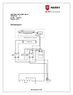
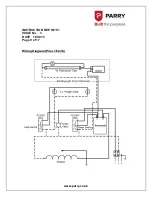
Страница 8: ...INSTRUCTION REF IN191 ISSUE No 3 DATE 18 08 15 Page 8 of 17 www parry co uk Wiring Diagram...

Страница 9: ...INSTRUCTION REF IN191 ISSUE No 3 DATE 18 08 15 Page 9 of 17 www parry co uk Wiring Diagram Prior 1 12 14...

Страница 10: ...INSTRUCTION REF IN191 ISSUE No 3 DATE 18 08 15 Page 10 of 17 www parry co uk EXPLODED VIEW PC140GB Shown...

Страница 11: ...X 1 X 1 10 Shelf PC140RACK X 5 X 5 X5 X 5 X 5 X 5 X 5 11 Humidity Tray AS3481TRY X 1 X 1 X1 X 1 X 1 X 1 X 1 12 Green Neon LNGN06378 X 1 X 1 X1 X 1 X 1 X 1 X 1 13 Round Illuminated Switch Prior 1 12 1...

Страница 12: ...1 X1 X 1 X1 X1 X1 33 Inner LH Panel X 1 X 1 X1 X 1 X1 X1 X1 34 100w Halogen Lamp Assembly CLIC100LAMP X 2 X 2 X2 X 2 X2 X2 X2 35 Branding Light Panel N A N A N A X 1 N A N A X1 35a Branding Light Pan...

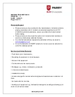
Страница 13: ...has not been carried out in accordance with the manufacturer s instructions See installation details Also the misuse alteration or unauthorised repairs of the equipment will invalidate the warranty D...

Страница 14: ...all warranty requests be submitted to Parry via email to warranty parry co uk It is at the discretion of PARRY whether to honour a service call which is out of the warranty period Not Covered Under Wa...

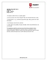
Страница 15: ...iring junction box fault wrong fuse Any damages caused by the customer Lamps glass door gaskets Perspex baskets knobs all perishable items are not covered This appliance should be routinely serviced t...

Страница 16: ...icates that this appliance may not be treated as household waste Instead it should be handed over to the applicable collection point for the recycling of electrical and electronic equipment Disposal m...

Страница 17: ...ty Contact the units manufacturer importer or their agent the contact details will be on the unit There will probably be a charge for this service which will depend on the physical size and location o...

Отзывы: