Parmco HO-3-6G-3GW Скачать руководство пользователя страница 6


4

0

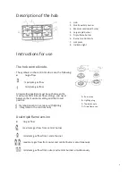
Description of the hob


Instructions for use 


The hob control knobs 

The symbols on the control knobs mean the following: 

Ɣ


no gas flow


      maximum gas flow 


minimum gas flow 


All operating positions must be set between the 

maximum and minimum flow settings, and never 

between the maximum setting and the closed 

position. 


(Symbol present on versions with lighting 

integrated in the control knob) 


Dual triple flame version 

Ɣ


no gas flow 

 
   maximum gas flow from central burner 


   minimum gas flow from central burner 


maximum gas flow from outer and central burners simultaneously  

 
minimum gas flow from outer and central burners simultaneously     


A – Burner cap 

B – Lighting plug 

C – Thermocouple 

D – Triple flame cap


1. Hob 
2. Small auxiliary burner 
3. Medium semi-rapid burner 
4. Large rapid burner 
5. Triple flame burner 
6. Burner control knobs 
7. Hot plate 
8. Indicator light

Содержание HO-3-6G-3GW

Страница 1: ...n and Operating Instructions W W K Models HO 1 6S 4G HO 1 2S 2G HO 1 6S 3GW HO 1 6W 3GW HO 2 6S 4G HO 2 75S 4GW HO 2 9S 4GW HO 3 6G 3GW HO 3 77G 4GW HO 3 9G 4GW HO 6 6S 3GW HO 6 77S 4GW HO 6 9S 4GW 72...

Страница 2: ...te of all detailed technical information and installation instructions It is essential that you only allow a qualified technician to install this appliance to ensure the safety and reliability of this...

Страница 3: ...bols ng the instr fety informa ep by step ggestions an ormation co is appliance 73 23 a 89 336 90 396 93 68 and su ance on Techn tallation tec nt types of hen units he instru will help yo ructions ati...

Страница 4: ...ondition Otherwise contact your dealer before putting the appliance into operation x The Manufacturer declines all responsibility in the case of failure to comply with accident prevention regulations...

Страница 5: ...his manual If you do not find the necessary information contact Parmco Service Department Servicing work on this appliance must be carried out by a qualified technician Always request the use of origi...

Страница 6: ...present on versions with lighting integrated in the control knob Dual triple flame version no gas flow maximum gas flow from central burner minimum gas flow from central burner maximum gas flow from o...

Страница 7: ...few attempts check that the burner cap and flame cap are correctly positioned To turn off the flame turn the control knob clockwise to the symbol Before removing pans from the burners always lower or...

Страница 8: ...er and a little liquid detergent Do not use the following products x household detergents or bleaches x soaped scouring pads not suitable for non stick utensils x steel wool scouring pads x stain remo...

Страница 9: ...necessary repairs or adjustments must be carried out with the greatest care and attention For this reason we strongly advise you always to contact the Dealer who sold you the appliance or Parmco Serv...

Страница 10: ...E Injector Size MJ h Injector Size MJ h Small auxiliary 0 66 3 23 0 50 2 93 Medium semi rapid 0 97 5 78 0 65 5 09 Large rapid 1 18 9 74 0 80 8 05 Triple flame 4 x 0 82 1 x 0 75 18 62 4 x 0 53 1 x 0 47...

Страница 11: ...placed close to the floor preferably on the side opposite to that on which the flue gases are discharged If it is not feasible to provide these openings in the room where the appliance is installed t...

Страница 12: ...the end of the gas train Complete with GJ threaded nut fit the gasket between the components as shown in the illustration The gaskets must comply with the local standards Screw the parts together wit...

Страница 13: ...liance and the mains with at least 3mm between the contacts of suitable rating for the load and complying with the regulations in force The switch must not break contact in the yellow green earth wire...

Страница 14: ...e supply pipeline Setting the minimum level 1 Light the burner as already described 2 Turn the tap to the minimum flame position 3 Remove the control knobs 4 LPG to NG Use a thin blade screwdriver to...

Страница 15: ...enly without gaps or overlapping in order to prevent liquid from seeping underneath the hob 1 Remove the pan stands and burners caps and turn the hob upside down taking care not to damage plugs and th...

Страница 16: ...g overheating are illustrated on the right The electrical connections of the hob and oven must be made separately both for electrical reasons and for simplifying the removal of the oven through the fr...

Страница 17: ...XUFKDVH FDQ EH IRU WKH SURGXFW LWVHOI RU LI LQVWDOOHG ZLWK D NLWFKHQ RU KRXVH WKHQ SURRI RI SXUFKDVH FDQ EH IURP D 3DUPFR UHVHOOHU RI SURGXFWV VXSSOLHG E 3DUPFR Liability under this warranty will not...

Отзывы: