14 GB
Start-up
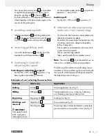
Function
Accessory
Application
Cleaning
Plastic brushes
30
e.g. cleaning hard to reach plastic housings or
cleaning the area around a door lock
Metal brush
31
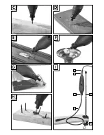
e.g. rust removal (see Fig. E)
(The metal brush is softer than steel)
Grinding
Grinding discs
21
Grinding stone
23
,
Grinding bits
20
Grinding stone, detail work on hard materials such
as ceramics or alloy steel (see Fig. G)
Sanding belts
24
Sanding wood
Cutting
Cutting discs
18
,
19
Processing metal, stone (see Fig. H)
Flexible shaft
Never use the spindle lock with the motor on.
The tool or the flexible shaft could otherwise
be damaged.
Unscrew the union nut
5
from the tool, turning
counter-clockwise, and put aside.
Press and hold the spindle lock
8
.
Unscrew the clamping nut
6
from the tool,
turning counter-clockwise.
Attach the flexible shaft
13
to the tool, inserting
the inner axle on the flexible shaft along with
the clamping nut
6
into the collet
7
.
Use the combination wrench
33
to first tighten the
clamping nut
6
, then the union nut
13 b
of the
flexible shaft
13
to the tool, turning clockwise.
Now insert the accessory you wish to use into
the collet
7
of the flexible shaft.
To lock the spindle, slide back the black sleeve
on the flexible shaft.
Using the combination wrench
33
, open the
collet holder
14
on the flexible shaft, insert the
accessory and tighten the collet holder
14
.
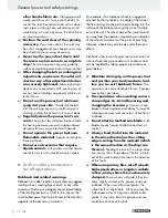
Stretch stand for the multi-func-
tion tool (Fig. I)
Screw the stretch stand
16
into the clamp
17
.
Note:
The stretch stand
16
can be screwed
into the clamp in two different positions, de-
pending on the whether you‘re attaching to a
horizontal or vertical surface.
Secure the clamp
17
at the edge of a work-
bench or a work table no thicker than 55 mm.
The stretch stand
16
is height adjustable. Loosen
the upper tube of the stretch stand
16
by turning
to the left (–). Extend the tube to the maximum
height and secure by turning to the right (+).
The holder
15
is also height adjustable, simple
turn the black thread to the left. After adjusting
the holder to the correct height, turn the thread
in the opposite direction to tighten.
Secure the tool to the holder
15
of the stretch
stand
16
with the metal bracket
3
. This hold-
er
15
rotates by 360°.
Base assembly
Using the attachment, the tool is particularly suited
for cutting special shapes (holes for sockets, etc.).
Attach the milling bit
27
as described in chapter
„Attaching / changing the tool / collet“.
Ensure that the bit’s shaft protrudes from collet
by approx. 13 mm.
Unscrew the union nut
5
from the tool, turning
clockwise, and put aside.
Screw the base
12
onto the unit.
To set the correct working depth, loosen the
locking screw
11
and adjust the bottom of the
base assembly to the desired size.
Then tighten the locking screw
11
.
Start-up / Cleaning, care and storage / Warranty


